Eric Wiiliam
This board is to make my life easier when measuring/probing unknown hardware. Often I want to hook up a logic probe or DMM in to the crcuit and manipulate the outputs- hence the dipswitches so I can turn things on or off
Buy a DIY kit in my store here: https://store.mkme.org/?product_cat=custom

🐦 Twitter | 📺 YouTube | 🌍 mkme.org
Support this project and become a patron on Eric's Patreon.
Website, Forum and store are at http://mkme.org
Chat with Me: Discord
The protoyping area will allow me to add any components INSIDE the working crcuit while measuring on the DUT- Handy eh?
You can add capacitance, resistance, switches LED indicators easily by putting them right in series or parell with the circuit
While the DIPswitch conenctions allow probing the lower connections are not joined in the center- this allows the user to either connect them or conenct with more components as mentioned above

Forum Thread HERE - https://forum.mkme.org
My Videos HERE: https://www.youtube.com/mkmeorg
Hardware:
Parts can be found in the KiCad BOM
Buy the PCB in my store: https://store.mkme.org/?product_cat=custom
Buy DIP switches on Amazon: https://amzn.to/2UbDWsz
Header pins colored : https://amzn.to/3euvvPY
Header pins black only https://amzn.to/3z3T4Xy

Project:
Base/Enclosure
While the initial design is off at PCBWay for board fab I decided to make a base to set the unit on.
To do this I used Kicad Plot and exported the Drill file as SVG see file ProbeMaster-PTH-drl_map:

I pulled this in to Inkscape and just traced the outline and plotted 4 3mm mounting holes aligning them with the PCB holes

This I can use easily in my K40 laser cutter to cut a nice acrylic base.
This work is licensed under a Creative Commons Attribution-NonCommercial 4.0 International License. https://creativecommons.org/licenses/by-nc/4.0/

 selena1995
 DIY GUY Chris
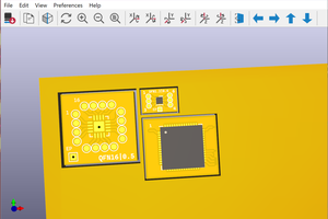
 Kumar, Abhishek