 Ted Yapo
I've been playing with a couple of circuits for driving LEDs with short, high-current pulses (so far up to about 10 amps per LED chip). At microsecond pulse lengths, this isn't the kind of current you get through wires from your supply; this is the kind of current you draw from local capacitors, planning the current path in tight loops to minimize inductance. So, I need some capacitors. I found some surprising things while researching them. Here are the three types I've looked into:
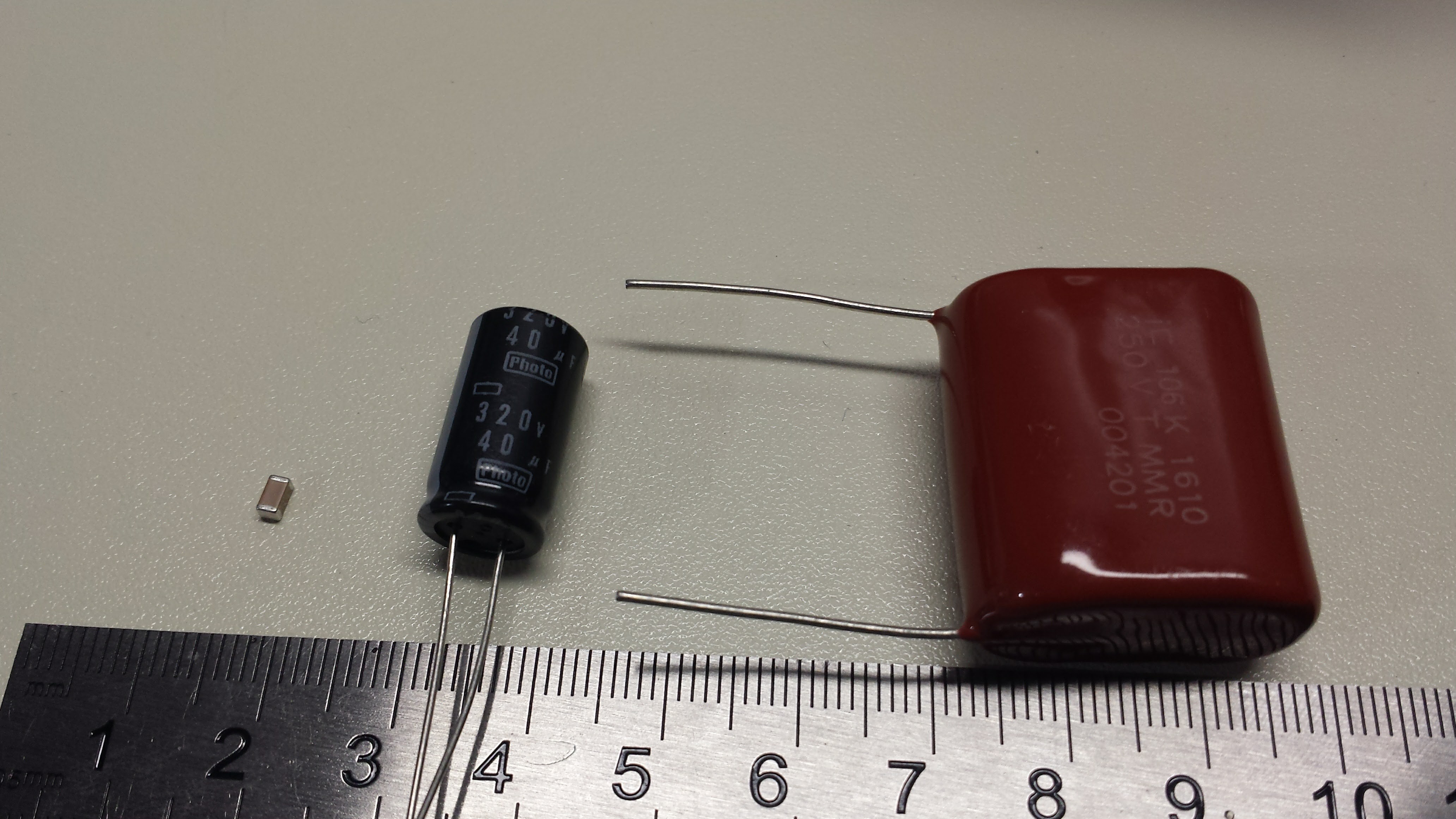
On the left is a 10uF 25V MLCC (1206 package). Center, we have a 40uF 320V photoflash capacitor. You don't find too many with smaller capacitance than this. Finally, we have a 10uF 250V metalized polyester capacitor. These things each have their drawbacks.
MLCC
The multi-layer ceramic capacitor is a modern wonder - how do they pack 10uF of capacitance into that tiny case? They use lousy dielectrics that lose most of their capacitance with applied voltage. Here's a curve I pulled from one of the datasheets for a 10uF 35V cap:
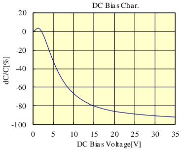
The curve shows the change in capacitance vs the applied voltage. If you use the capacitor at the rated voltage, you lose more than 90% of the capacitance - the 10uF is now less than 1uF. Of course, you always de-rate components, but even if you de-rate this voltage by a factor of 2.3 and use the cap at 15V, you've still lost 80% of the original 10uF. This graph is for an X7R dielectric, which is specified for +/-15%, but that has to do with changes over temperature, not applied voltage.
They're not all this bad. I couldn't find this graph for the capacitors I've been using, but the loss of capacitance at higher voltage is clear from the waveforms produced (detailed in the next log). A possible (expensive) workaround is to parallel many of these capacitors so that you end up with the desired capacitance at the working voltage. Even with 5 of them paralleled on my test board, I still see problems.
The second problem with these capacitors is that the dielectric is typically piezoelectric. In sensitive circuits you can get microphonic noise introduced into your signals. In my case, I have the opposite issue - the capacitors issue a troubling "snap" noise each time the LEDs are pulsed. I can only wonder if this mechanical stress will eventually damage the capacitors. I've had MLCC's "sing" before in circuits, and while it's annoying, I had never feared for their safety. This time, I'm not so sure.
Finally, these caps seem to top out at around 50V ratings. I had hoped to keep the LED flash circuits strictly low-voltage to make them safer than xenon flashtube versions, but driving high currents into strings of LEDs looks like it will take some higher voltages.
After experimenting with theses caps for a while, I've decided to look at the other two.
Photoflash Electrolytics
The second suspect is the capacitor behind the typical xenon flashtube. These high-voltage electrolytics are designed to have low ESR (equivalent series resistance) and ESL (equivalent series inductance) so they can deliver high-current pulses in the millisecond range or so. Normal electrolytics, even higher voltage types, typically aren't rated for the high pulse currents involved. I haven't tried this particular cap in the flash circuit yet, but I worry that the ESL will be too high to generate very short pulses. I can't find any specs on ESL for these, so I'll just have to try them. Electrolytic caps also have a lousy lifetime, but they're cheaper than the film types below.
Another drawback is that these specialized capacitors aren't typically stocked by the usual, reliable distributors. I was forced to find some on ebay. Who knows what I actually got.
Metalized Polyester
The last cap is probably electrically the best. I chose some 10uf 250V caps made by Illinois Capacitor - I won't be using voltages this high, but chose this unit for the current rating. These capacitors are rated for a maximum dV/dt of 15 V/us. For a 10uF capacitor, that translates to a current of 150A. I figure I can safely use them for 100A pulses or more while maintaining a healthy de-rating. As far as ESL, the datasheet states less than 1nH per mm of body and lead length - probably around 40nH mounted on a PCB - not bad at all. Finally, the ESR can be estimated from the dissipation factor, which is rated less than 1%. This document explains dissipation factor, which is:
where Xc is the capacitive reactance at the test frequency. At the 1 kHz test frequency, a 10uF capacitor has a reactance of:
So, the ESR should be less than 1% of 15.9 ohms or 159 milliohms. A 100A pulse would drop a maximum 16 volts across the ESR - with a maximum of 250V to play with, we can just crank the voltage to compensate.
The downsides are that these capacitors are huuuuge and expensive.
EDIT 20161115
I forgot to mention that some of my thoughts about capacitor selection were influenced by Don Klipsein's notes about bullet photography with traditional flashlamps. His advice is to use the foil types for the kV-level voltages involved in that kind of ultra-short xenon flash driver. My thought was that if they can deliver microsecond pulses to flashlamps, they can do the same for LEDs. Of course, with LEDs, you can easily control the flash duration by switching off the driver, instead of relying on a small capacitor to fully discharge.
Discussions
Become a Hackaday.io Member
Create an account to leave a comment. Already have an account? Log In.
In a way Ted, it is like a battery, but it holds it's charge until needed, the dielectric constant of the KBr substrate can be extremely large, and rise time on a molecular level, the idea is not exactly new, but difficult to incorporate. Redistribution of fall time is at the same velocity, so fast switching takes on a new definition.
Are you sure? yes | no
Yes, capacitors are amazing little darlings but limited by their material design. I do have a project in the background, where I am working on using a potassium bromide substrate in either a gel or more density firm structure, the idea begin that REDOX reactions have a far more accurate and predictable guide line than electrolytics or di-electrics, and can retain a capacitive charge far longer than metalic substrates.
Are you sure? yes | no
REDOX reactions makes it sound like a battery instead of a capacitor? Maybe some kind of hybrid is what's really needed - the energy density of batteries with the power density of capacitors.
Are you sure? yes | no
What about ultracapacitors, polymer cap etc?
http://www.cap-xx.com/wp-content/uploads/2015/04/Using-Supercapacitors-to-Solve-LED-Flash-Power-Issues-for-High-Res-CamPhones.pdf
http://www.mouser.com/pdfdocs/Panasonic_Capacitors_WP_final.PDF
The trick isn't finding small values caps. You can also switch the LED with MOSFET from a high current source e.g. ultracap
Timing in us isn't hard as switch mode supplies can be designed to deliver high current and high slew rates. e.g. CPU VRM.
Are you sure? yes | no
Interesting points.
I didn't mean to imply that small capacitors are required, only that there's no need to pay for larger ones for such short pulses :-)
I saw similar papers to the one you linked about the ultracap for cell-phone flashes, but it's a different problem. They can afford 150ms flashes; I'm looking at flashes 5 orders of magnitude shorter. My suspicion is that the ESL of the ultracaps would be too high, but this is a wild guess. More importantly, ultracaps are also low-voltage rated (like 5.5V). Even a single LED chip ends up with a Vf of more than 5.5 at very high currents (partly due to the internal series resistance) - and the LED packages I'm looking at driving have at least three LEDs in series, so I need tens of volts (at least) to generate the pulses - I will probably end up needing more than 50V based on estimates of how many I need to run in series and required currents. You could put ultracaps in series with balancing R's (even the linked paper needs two of them), but that adds cost.
Polymer caps are better, but if I use their ripple current rating as a max pulse limit, they still come up short. I know that the ripple current rating is typically based on thermal issues (which aren't an issue here), but the film caps seem explicitly rated for low ESR, ESL, high voltage, and high discharge currents, so I can accept the size and cost.
Yes, the switching isn't hard - and MOSFETs are the way to go. I have a NCP81074 MOSFET gate driver (4ns rise/fall) and an FDD6630A MOSFET driving clean 20+A 1us pulses into some LEDs on the bench at the moment (writeup to come soon :-)
http://www.onsemi.com/pub_link/Collateral/NCP81074-D.PDF
https://www.fairchildsemi.com/datasheets/FD/FDD6630A.pdf
These pulses, into two series connected LEDs, require a 24V supply. This was using parts I had around from other projects; I have some better ones to try, also.
I initially tried with BJTs, but storage time was a limiting factor in getting the short pulses. Maybe I'll write it up as an interesting "fail"
Are you sure? yes | no
Lot of rail gun and coil guns project are built using high voltage electrolytics. Those are much better documented than photoflash caps. Can't beat the energy storage capacity per cost.
If you don't care about efficiency, a higher voltage (than the LED rating) can be used to overcome parasitics and droops. Now it becomes a problem of limiting voltage/current fed into the LED array.
Are you sure? yes | no
I hadn't thought about checking out coil gun projects - In the past, I somehow got the feeling that many of them were less "designed" than I might find useful. I'll have a look...
Are you sure? yes | no
Did a bit of quick simulation using my discrete switch mode supply. It looks promising.
https://hackaday.io/project/2145-smps-replacement-for-7805/log/49101-led-photoflash
This is the output voltage vs LED current when the LED is fired for 5us.
The cap model isn't that good as it doesn't have the ESL. The voltage setpoint can be used to compensate for that. Larger inductance could be used.
Seems like the 1uH is a good initial guess as the current is more or less constant during the flash. At 3.3uH, it maintains a constant current.
Are you sure? yes | no
This is interesting. I'm going to have to take a closer look here.
Are you sure? yes | no
Excelent reminder of the "hiden" characteristics of these parts !
Are you sure? yes | no