 Sagar 001
Hello everyone, good to see you back here. Today in this tutorial we are going to make a preamp circuit without using any kind of transistor or ic. This preamplifier circuit will able to control and adjust Bass, Treble and volume manually.
In this tutorial we are making two preamplifier (Bass, treble and volume control) circuits.I will demonstrate you how both the circuits and different from each other. In the section a Youtube video is embedded so that we can easily compare both the circuits.
Preamplifier:

This is a complex circuit which is used to modify the sound signal before giving it to main power amplifier. Because sound signal consists a lot of up-down frequency curves. For Bass we need low frequency signal instead of high, so high frequency is cut-off by the circuit. Similarly in treble we need high frequency for better response. That’s why we are designing a preamp to make the overall signal (bass-treble and volume) adjustable.

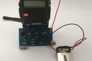
This is the prototype PCB for the same circuit.
Circuit components:
For mono-amplifier board:
- 4pcs 100nf polyester film capacitor
- 2pcs 1k 0.25-ohm resistor
- 3pcs potentiometers (signal channel)
For stereo-amplifier board:
- 8pcs 100nf polyester film capacitor
- 4pcs 1k 0.25-ohm resistor
- 3pcs potentiometers (stereo-double channel)
Circuit diagram:

Download all files regarding this project.
Gerber files:

Circuit description:
Here we are using three potentiometers (two of 100k and one of 50k). by 100k potentiometers we can adjust Bass and Treble. Volume level can be controlled using 50k potentiometer. In this circuit we will only use passive components that’s why project become much simpler.
Polyester film 100nF capacitors and 1kohm 0.25 watts resistors are used in this circuit. We can choose some close values to them.
To make this circuit compatible to stereo amplifier we have to use stereo double potentiometers and all the components are doubled then.
Result:
After reviewing this circuit and making some noise with this, everything is going fine but passive components are not able to cut the frequency curve as desired so I changed my mind and then go for prototype PCB.
*The above circuit is very good and will be work fine, for more follow the next circuit.
For that I discover some circuits on internet then make the schematics accordingly. This time we sent our files to JLCPCB to get best prototype board.
Gerber files:
Download all the files from here.


Circuit components:
- Potentiometer (100k, 50k)
- Capacitors (4.7uf, 220uf)
- Bc548 transistor
- Resistors (150k, 100k, 47k, 10k, 6.8k, 1k)
- Polyester film capacitors (220pf, 100nf, 47nf)
- Screw terminal
Circuit description:
this is a stereo preamplifier circuit and through this we can control bass, treble and volume of the sound signal in a very professional way. This circuit has good frequency response. All the components used here are easily available in online or offline market. This circuit basically follows the same phenomena as above one but one step modified. To power up the transistor circuit we have to supply +12 volt to this circuit.
Result:
Overall sound control is good, there is no any type of humming. For more better response, we can use high quality capacitors and resistors.
For more circuits and detailed description follow us on Instagram page. This circuit can me modified more for best results till then stay tuned with us.
PCB designs and making:
We can make pcb at home or we can use breadboard to develop this circuit but for better performance and simplicity we made a circuit using EasyEDA and then order the PCB from JLCPCB

I made some changes in the PCB circuit, originally it was made by electro India so all credit goes to him.
Video:
This is video information about this project. This video has all information regarding soldering and components placing. Watch this video to listen speaker sound and bass.
 YTURacing
 Mrinnovative