Super Simple MW/AM radio circuit
A one transistor MW/AM radio.
A one transistor MW/AM radio.
To make the experience fit your profile, pick a username and tell us what interests you.
We found and based on your interests.
It seemed to be within reach so I had a go. Here is my design:
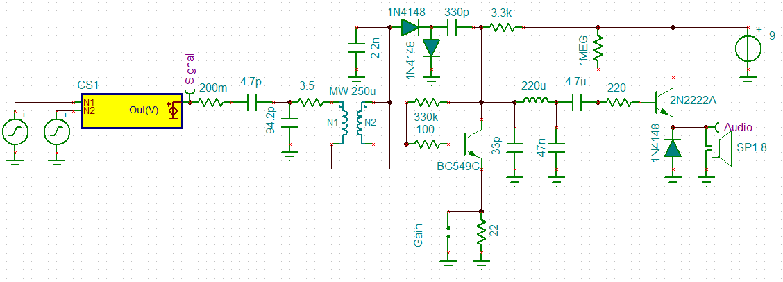
The idea behind the "gain" switch is to reduce the gain (open) for loud station in order to reduce distortion.
Works well. Volume out of a small 5w speaker was quite adequate for home use.
Voice was fine but music was badly distorted. Reducing the gain did not help.
A single sided class B audio amplifier is not going to help either.
I think the receiver is too selective for music.
I should have stayed with the 3 turn coupling coil rather than changing to 2 turns.
I think I am ready to "box up" this receiver and call it done.
I had a go at designing a MW PCB coil:
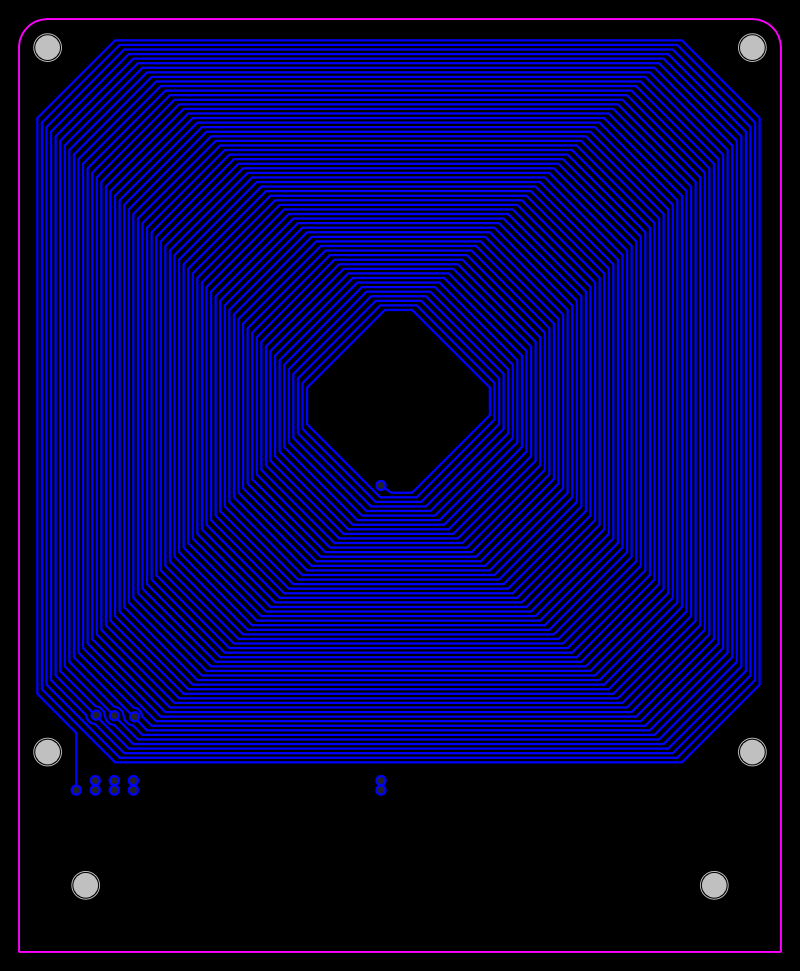
Unfortunately the Q of these coil is quite low (~40 for 1 Oz copper and ~60 for 2 oz copper) but the self resonance is about 1.8 MHz.
I suspect that to use these coils a regenerative design may be required.
Decided to rewind the coupling coil from 2 turns to 4 turns.
Louder (expected), less selective (but still too selective) and much less distortion.
For MW/AM I think 6 or 8 turns may be better.
The gain switch resistor may need to be increased from 22R to 33R or 47R.
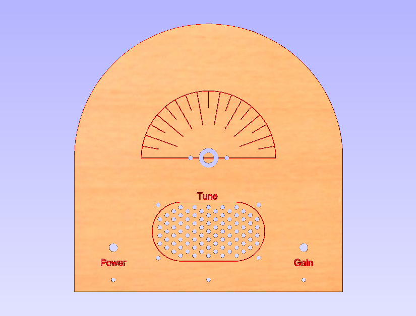
I made up a front panel (done):
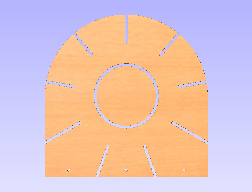
And a matching new coil former for 0.63 mm diameter wire (to be completed):
Here is the finished project:
And:
Several problems with the set:
I swapped out the coil for a PCB version and it works but nowhere near as loud:
The PCB coil has very low Q (about 44) but selectivity is okay in this application. The reflex has some regeneration.
Distortion is much better with this coil.
If I want more volume I will have to swap out the 9v battery and use some AAs (i.e. 3v) as they will last longer. I will also have to change some resistor values.
The distortion makes this receiver disappointing. The problem is not with the Class B audio amplifier as the problem exists with a crystal earpiece.
I originally thought that the problem was because the receiver was too selective but the problem persists even with the low Q coil.
Although the receiver is called a Reflex and the RF is decoded by the diode network and re-amplified by the first transistor it is not quite that simple. It is also regenerative because it does matter which way the coupling coil is linked up.
The diode detector is acting as a square law detector with unit gain around 100 uV to 1 mv because the audio voltage increases as a square of the input voltage. But I think it is also regulating the regenerative feedback. I am starting to think that in the presence of a signal the receiver goes into oscillation (or the level of oscillation increases) and demodulation is more mixing than square law detection. Particularly as the diode network is unbiased.
As per the "synchronous detector" I built, if over-driven (i.e. too much feedback), the demodulation becomes chaotic (i.e. distorted). This chaotic behaviour is probably equivalent to parasitic oscillation.
So I suspect the distortion is actually parasitic oscillation. The solution may be to increase the value of the 100R base resistor to say 220R or higher.
Tried the 220R resistor improved but not fixed, 330R improves a little more but reduces sensitivity. It seems the remaining distortion is for strong stations and mostly in the Class B amplifier. Is it the Class B or parasitic oscillation? Perhaps I should increase the base for the Class B as well.
Well, 330R works a bit better but using the oscilloscope shows the audio saturating (may be going into oscillation?) in the first stage. The saturation shows up as an exponential spike on the audio. So the only option now is the gain control "emitter"...
Read more »I knocked up this circuit as it claims so much (there is a version with a speaker transformer that claims loud speaker performance from two transistors) and is so simple:
The regeneration/gain control is a little strange (the gain will go down and then back up, as the regeneration feedback increases) but in practice it works very well.
Actually better than the reflex! The only strange thing was that from time to time it just stops by itself and I have to wind the regeneration to zero and back up again (or power off)?! It may be C4 playing games? The circuit probably needs a bypass capacitor from the collector of T2 to ground as well.
For transistors I just used the BC548B.
There is another version of this receiver with different component values:
http://www.homemade-circuits.com/2012/10/simplest-am-radio-receiver-with-speaker.html
I used his image but added the component values:
This circuit will work much better with an audio transformer.
The problem is that the audio transformers are the crappy small ones of the expensive (but still crappy) big ones.
So I decided to use a small potted AC transformer.
Found a PCB mount 0.3VA 220v to 18v job (equal to 1200 ohm to 8 ohm) that will be perfect for these radios for A$8/each.
I have been analysing this circuit and I am not that impressed (any more):
A lot of gain has been lost due to the emitter LCR network.I should look at alternate biasing methods.
I am am now looking at this reflex:
I will have to model it to see how it compares. Here is the model:The 33 mH choke is a bit of over the top, 1m works just as well.
I reworked the component values and got a big improvement in the simulator (x10):
Modelling a one transistor reflex.
There are a number of schematics on the Internet.
Here is a very simple one (the 636):
And a video from the Internet:
Here is my simulation of my version:
A number of changes were made:
The schematic consists of:
Analysis:
Replacing the 1 mH inductor with a 1k resistor, this reduced the gain by a factor of 3.
Increasing the tuning coil tap to 20% kills the tuning coil Q.
Here is another version that uses a higher coupling tap but uses regeneration (L3) to "fix" the Q (but L2 looks to be the wrong way?):
(source: http://electronicdesign.com/analog/rediscover-truly-tunable-hall-network)
Optimisations in a simulator can be false!
So the results should be reviewed to determine if they are reasonable.
I have had overly unrealistic performance from a simulator for my diode transistor NAND gates (at least 10x better than reality).
So I am getting very good improvements with the 636 reflex receiver but I think they are believable!
One thing I noticed with Rick Anderson's receiver above is that the 0.001uF capacitor from the collector of transistor 1 to ground was necessary.
At first I glance it appeared to be part of the low pass pi filter.
It was a little strange as it bypasses RF to ground in competition with the diode.
Reducing the value 10 fold improved performance (10 fold) but total removal killed the circuit?
So I added this the the 636 reflex and got a huge improvement:
I also set the audio load to that of a transistor audio amplifier....
Read more »I modelled the Reflex (I could not get the coil tap to work properly but I got a capacitive tap to work):
The input impedance to the first stage is dominated by the diode impedance (~70 ohm).
This explains the 1:10 tap of the original circuit.
As the receiver noise is already high the best way to improve the receiver is with a pre-amp or an impedance matching buffer:
The buffer has a 15k input impedance so no impedance tap is required.
AlanX
I assembled the two transistor reflex circuit:
I went with this design as I have built it before and it works.
I did model this circuit in the simulator and the Ge diode can be swapped with a silicon (the diode bias current is about 1.8 uA).
Also the audio output increases as a square of the signal strength (interesting?).
Well the performance was poor, I could just make out a local 720 kHz station.
So I think the circuit is working properly, just low signal?
Here is the reflex:
And here is the DIYLC design:
Th only change was to reduce the 100 uF emitter by pass to to 27 uF (25 uF would have been better) to centre the audio gain at 1 kHz.
AlanX
Long long ago I built a valve MW reflex receiver.
I could not get it to work so it went into the shed.
I can't remember how many years it has been in the shed.
Anyway with my revisit of MW receivers I pulled it out as a base for further experiments.
First I check the batteries and they were dead an I could not revive them.
Not a good idea to use sealed lead batteries in this type of project!
Next I saw that fake 15 mH choke (that is really a 15 uH choke).
Now the 15 mH choke was light on for this radio so 15 uH was the reason it did not work.
I had the ground and antenna hooked up the wrong way as well.
Anyway, no batteries so I pull it apart to try it out as a crystal set.
Here is the set in pieces:
And here is the fake 15mH next to a real one:
You can see that circuit board was made using a hacksaw to cut the copper foil!
Anyway, I put up a 15 m long-wire aerial and a ground, added a Ge diode and listened for any MW stations using a crystal ear-piece.
Pretty poor. I could just detect a station on 720 kHz at the top end of the tuning range.
As the coil has not taps and the diode was across top of the coil the selectivity was dreadful.
So what was wrong?
First the coil is far from optimal with too much self-capacitance. The L/D is about 1.5 while the optimal L/D is about 0.5.
Second, the wire spacing should be about 1 to 1 not close wound as I have done.
Third, the black coil former is likely black as it has graphite in it, not good for Q.
And lastly no impedance taps for the diode.
So that coil will have to go.
As a base for further experiments there is an old design I have used (long long ago) that works very well:
But I have gone with this one but less the audio amp:
(source: http://www.techlib.com/electronics/reflex.htm)
The Ic is about 1.1 mA and the diode bias about 3 uA.
This author has a preference for aerial loops which I rather like.
Here is the strip-board layout:
After a bit of research I elected to build a spider coil.
I had 14 m of 1 mm diameter enamel coated copper wire (which I thought would be enough - wrong!).
I designed for 250 uH, here is the web after I ran out of wire (24 turns out of 37 turns):
Two mistakes:
I will finish this design but the next one will use 0.8 mm wire.
The diameter of the coil frame is 200 mm (8 inches).
The design has 34 antenna turns and 3 coupling turns.
Too hard to get enough 1 mm diameter wire so I dropped down to 0.8 mm diameter wire and redesigned the coil.
Here is the finished coil:
And another view:
This coil is 32 turns total, 29 for the antenna coil and 3 for the coupling coil.
I was designed for a reflex set up.
I am staring to think the ratio 10:1 may be a bit extreme.
This was based on the design from http://www.techlib.com/electronics/reflex.htm.
It had 20 turns and 2 turns.
The problem with 10:1 is it is not much good for a crystal set.
Something like 2:1 or 3:1 would be better for a crystal set.
I can rewind the coupling coil to increase the turns later if needed.
As a crystal set this coil is just as bad as the first one due to over-loading by the diode and ear-piece.
It does not seem that reception of MW signals is not that great where I am located.
AlanX
Create an account to leave a comment. Already have an account? Log In.
I am very interested in your testing of this simple radio circuits.
So i have question :
Do you can recommend any simple design that work best
on shortwave from 3- 30 Mhz.
Also you may visit my site/forum at:
http://euradioboard.createmybb3.com/index.php
all best Aurel
I can't remember how many simple receivers I have soldered and I loved them all. Brings back fond memories. Guess I need to start building again.
Become a member to follow this project and never miss any updates
 Zach Armstrong
 agp.cooper
 Andrea Console
 DeepSOIC
Hi AlanX
I have a question:
How perform first PNP one transistor reflex am receiver?
I see that you use general purpose BC548 and why you dont use
RF transistors like BF254 or N9018 or similar?