 RachelAnne
A protection diode is connected in a circuit by placing the diode in series with the circuitry that is to be protected. For example, in this small project, we're going to connect the protection diode in series with an LED. An LED is pretty sensitive to current in the reverse direction. It can only handle a certain amount of current in the wrong direction. If enough reverse voltage drops across the LED, the LED will break down and allow current to flow through it in the reverse direction, which can cause the LED to be permanently damaged
Parts Needed for this Project
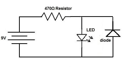
Below is the schematic which we will build for this circuit:
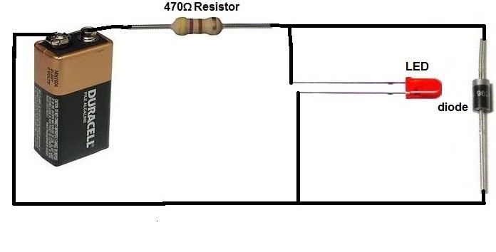
Now this is a more real life-like representation of the above circuit:
This circuit now protects against reverse current that could damage electronic components such as an LED. If a user places the battery in the wrong direction in the circuit, current will flow through the diode and then through the resistor or to the anode of the LED, bypassing the cathode of the LED. This means that the LED will not be damaged when a high reverse current flows through the circuit.
When current is flowing in the forward direction, it simply flows through the resistor, through the LED, and to ground.
Protection diodes are placed in many electronic circuitry devices to protect from reverse currents that could damage electronic components. If you think about gameboys, you've probably placed batteries in them with the wrong polarity orientation when putting in batteries in the back of them. If they weren't equipped with diodes in the circuitry, the gameboy could be damaged for good if the batteries were placed in the wrong way. But the diodes protect their internal circuitry against reverse current, so that when you place them in the right way, the gameboy still works.

 Keith
Keith
 Pavel
Pavel
 mattko