 tdw
tdw
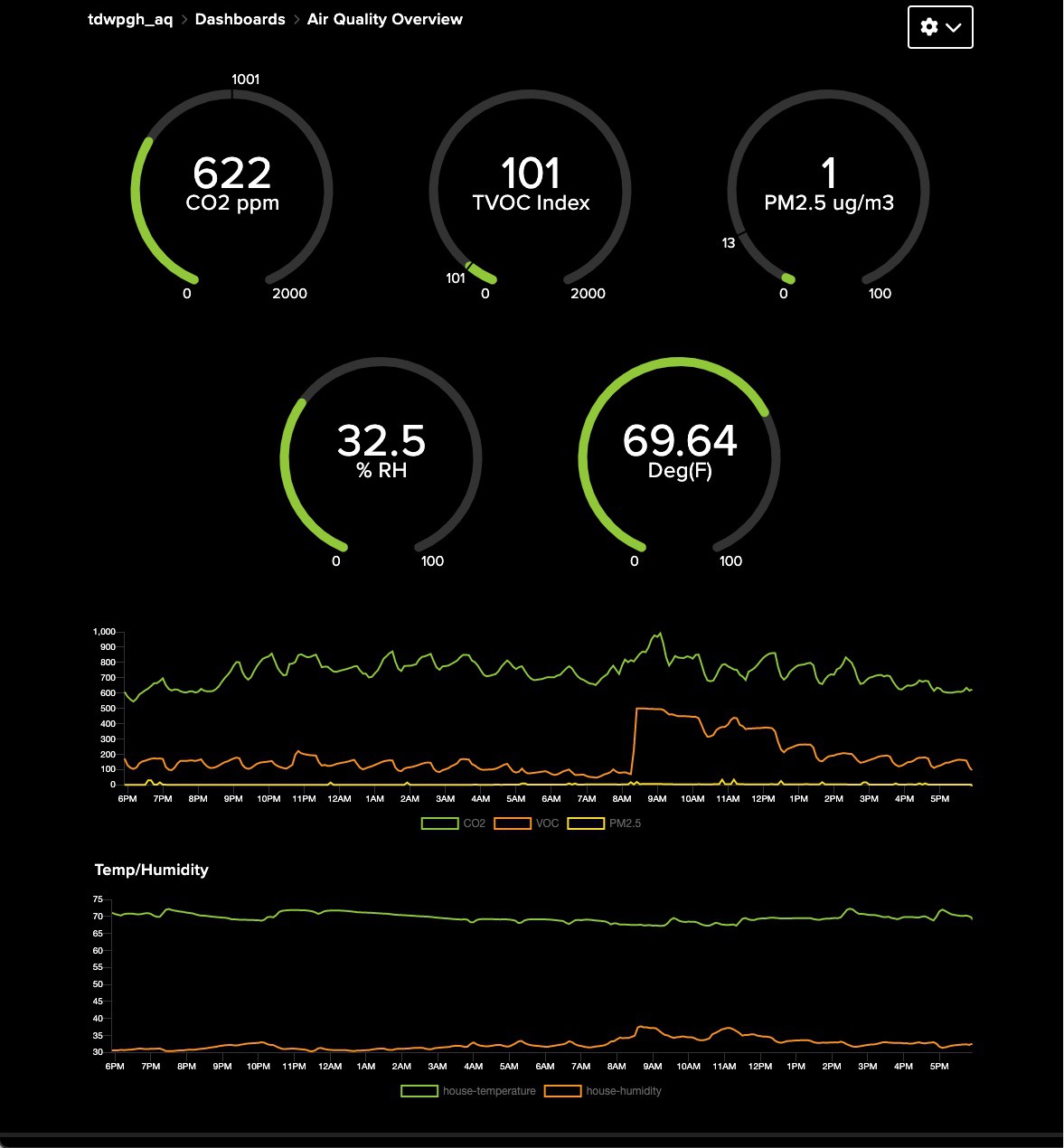
Note: With the breadboard design, I found that the CO2 concentration in my house was too high at various points throughout the day. VOC's tended to peak here and there, but not into what I'd generally be concerned about. When I added the PM2.5 sensor, I was able to correlate things like high-pollen days and air-quality notices, which gave me confidence in the data I was seeing... Among other reasons, this was primary in helping me decide to do a PCB for the project. Using the data I collected, I was able to adjust a number of things in our home, which in turn brought the CO2 and VOC levels much more into line with recommended levels. Take a look here for some details about what I found and how I dealt with it. If you're curious about my home's current indoor air-quality, this link will show you.
As I was working on the schematic, I started wondering if maybe this could be used as more of an experimenter platform, allowing me to test out various sensors and do some code to support them both locally and in the cloud. At that point, I decided to design the circuit/PCB in that direction.
I wanted to make it easy to build, easy to program for and flexible about what processor is used. I also wanted to make sure there was some kind of user-input and some kind of output available in case anyone wanted to have something interactive or just needed to see what the thing is doing.
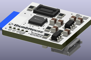
With those criteria in mind, here is a summary of the result:
- The board makes nearly exclusive use of through-hole design, so it should be easy to build for someone with basic soldering skills. It's a 2-layer design and is pretty inexpensive.
- It's powered from a common micro-USB connector and power brick.
- It provides a rotary encoder (with button), along with two other discrete buttons. These meet my criteria for having some form of user input.
- It supports both the Espressif ESP32 DevKit module footprint, as well as the common Feather module form-factor (Testing of feather boards is ongoing. So far the AdaFruit Feather Huzzah 8266, Feather M0 AdaLogger, & Feather ESP32-S2 boards have been tried). This allows for considerable choice regarding which processor module you want to use.
- It has a header for a simple I2C OLED display. Several compatible displays are available from places like AdaFruit and SparkFun.
- The board targets use of I2C and SPI sensors or other similar devices. There are header landing-pads for three I2C sensors, and headers for an added 2 SPI devices.
- There is a header for a UART-based device.
- The GPIO that is used for the rotary-encoder and pushbuttons is brought out to a header in case you choose not to use those devices.
- Each of the connection points for I2C and SPI devices can be populated with either a socket header or a pin header, depending upon your needs.
- There are test points for the +5V and +3.3V power supplies.
- There's even a helpful little LED that indicates if the +3.3V supply is powered.
- There are a variety of mounting holes on the board so you can mount the sensors you choose.
I mainly used the Arduino environment for the code part. That's certainly not required and many of the Feather modules that are available can run MicroPython or CircuitPython. As I also mentioned, I use Adafruit.io to provide IoT cloud connectivity. They have a great product and for what many people need, the free tier is more than sufficient. I've tried out a variety of other offerings and for my taste and pocketbook, Adafruit is a winner.
Note: f you want to see the air-quality in my home, look here. If you don't have an Adafruit.io account, the data won't update on its own, so you'll need to refresh the page if you want to see changes. (This is running on an Adafruit Feather Huzzah, 8266)
The schematic and printed circuit board were designed with KiCad and I used PCBWay to prototype the boards. I've used them...
Read more »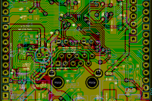
 Matias N.
 Justin