 Muth
MuthWe are back to glowing neon plasma, with yet another clock. The aim is to make some presents to offer to the family, for the end of the year. I previously made a little 6 tubes clock, that was inspired by Dalibor’s Zen clock. Here I want to mimic his amazing single tube Bulb clock.
Tube choice
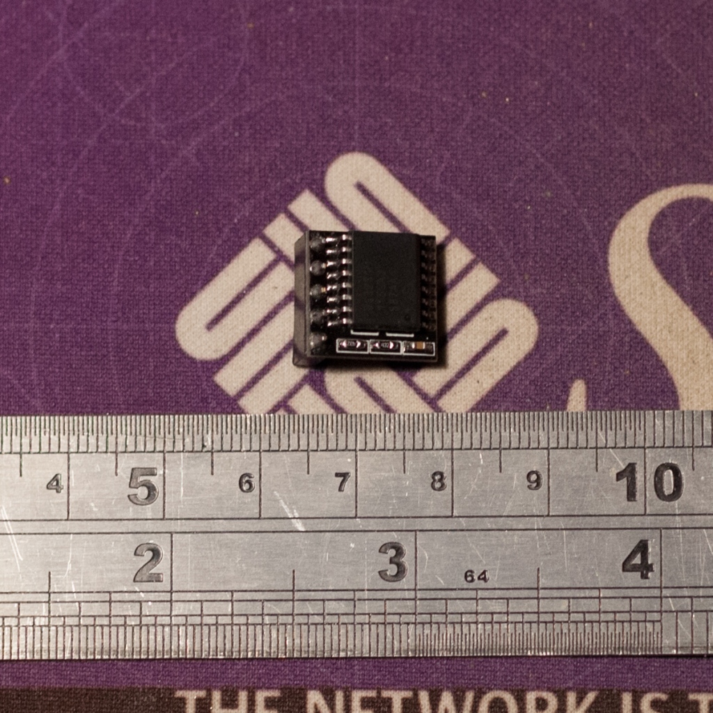
The smallest tube I have is a NEC LD-8007 (right), which I used for the 6 tube clock. However I’d rather keep it as a spare. I also have some LD-955a (center) and IN-16 (left), it is a good opportunity to use them.

Design constraints
In order to keep as much as possible the ratio of the original Bulb clock, the electronic board has to be rather compact.
For convenience, the power should come from a standard USB plug. I could use the same type of small high voltage power supply from NeonPixels. It is compact and a single digit does only require 1 to 2 mA. However we need to reach at least 170 Volts, so the components should be resized accordingly. Plus, I’d like to have a voltage measurement, with a cut-off threshold in order to not burn the components.
To keep track of the time, Real Time Clock [RTC] chips such as the DS3231 comes in handy boards with integrated back-up battery. So let’s use them directly.
The selection of the digit to light-up, or in other words the cathode to be grounded, can be achieved by using individual transistors. We will gain flexibility on the component placement compare to larger integrated circuits.
The micro-controller should then have sufficient IO to:
- Drive the high voltage step-up power supply.
- Acquire the output voltage and cut the HV drive if greater than 200V.
- Have two input for control buttons.
- Drive the 10 cathode transistors plus a decimal point.
- connect to the I2C port of the RTC.
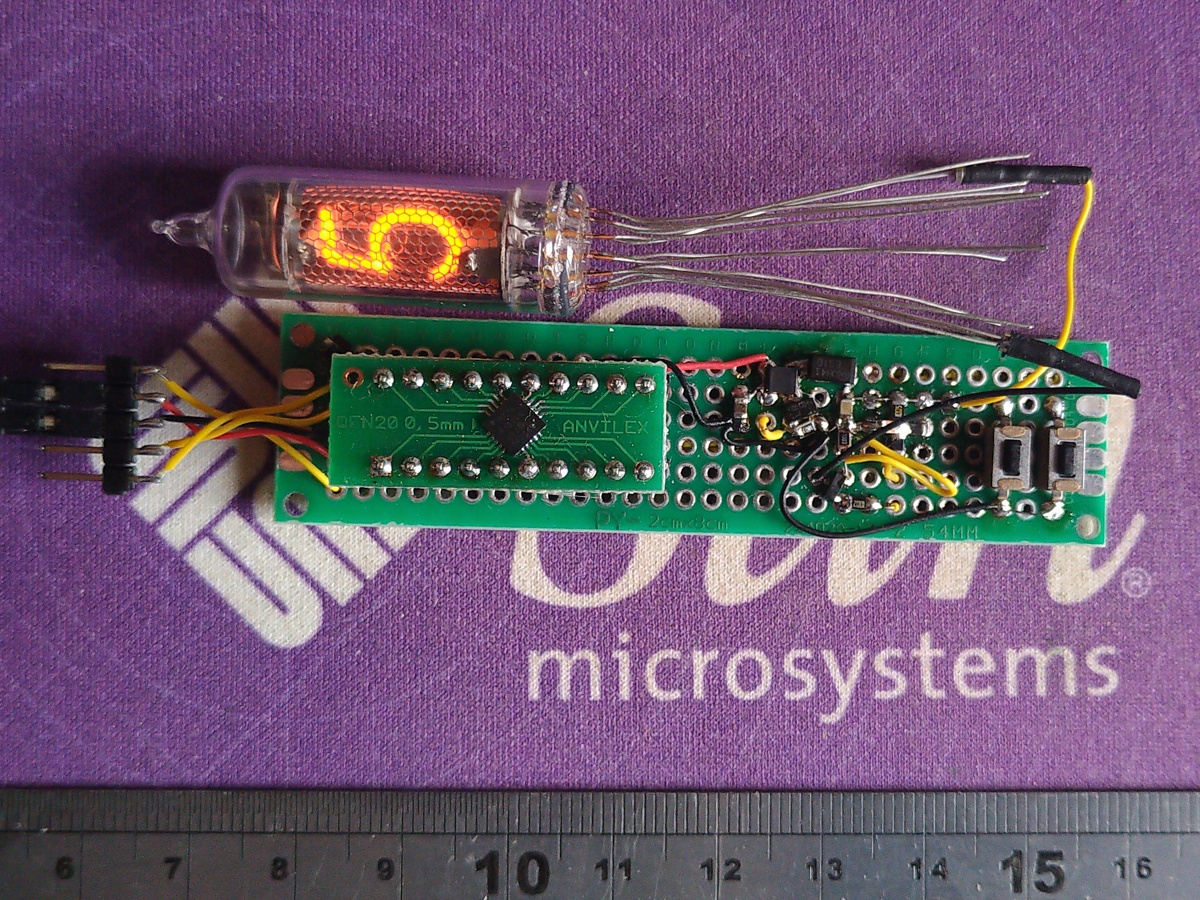
After some cross check between Microchip PIC parametric search and the chips availability during this 2021 global shortage period, I decided to go with the PIC16F18346. It has just the right number of IO, and comes in a small 20 pins QFN package.
Making
After some tests on a proto board, it appears we can easily reach 200 Volts at few milliamperes. I selected a 10uH coil, ES1D fast diode and BSS87 mosfet. The switching frequency is 100KHz at 20% duty cycle.
Below on the left is the output voltage. It starts with the ramp-up until it reaches the striking voltage of 170V, then it stabilize at the sustain voltage of 130V.

The next step now is to start Kicad and draw the schematics:

The PCB was quite fun to draw. I started with a 4 layers design, not sure I could do it with 2 layers. I payed attention to isolate the high voltage parts and have large power tracks. Even if it will be hidden, I tried to keep the top layer ‘aesthetic’.


I ordered the board on OSHPark (oshpark.com/shared_projects/WM4Mp7db) and JLCPCB. JLC is really fast, literally 7 days between the file upload and the mailbox delivery, plus the boards are completely cut. While OSHpark is slower and board cuts need sanding, they have a really better silkscreen.


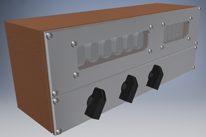
I draw the enclosure with Fusion360, and printed with a Prusa i3 MK3. It is a rather simple design and the board is hold in place by a circular clip.


Coding is done with MPLAB, and Code Composer is really convenient to setup all the peripherals. I have the high voltage power supply switching at 100KHz done by one PWM, another PWM at 500Hz for the brightness control, and a comparator measuring the high voltage versus a fix threshold. All of these going to an AND gate and drive the Mosfet. In addition I have the I2C peripheral for the RTC chip and a timer for the button features.
One button increases the hours with short press and increases the brightness with a long press. The second button does the same with the minutes and decreases the brightness with a long press.

About efficiency, of course this type of high voltage power supply is not the best. However, considering the small amount of power, it is not so bad.
... Read more »

 Charles Ahrens
 Paul Andrews
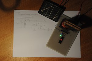
 Matthias Koch
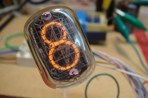
 The Reverend
Wow, I enjoyed reading your very detailed construction story, with great photos. 👍 No surprise when I saw that you did the Neon Pixels project too.