 Gertlex
Part 1: Disassembly
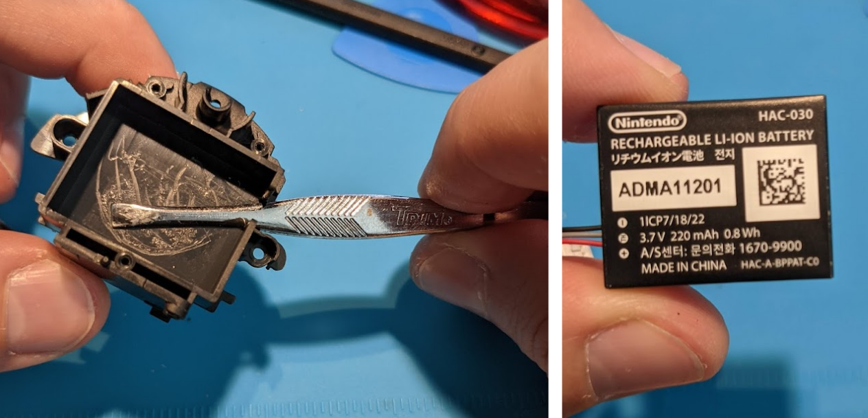
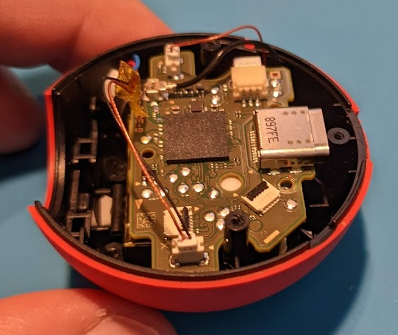
The battery was a hard case Li-Ion battery and surrounded by a whole additional plastic molding. I was able to get a pair of sturdy tweezers in between the battery and adhesive, and free the battery from the extra molding.
Part 2: Ideas
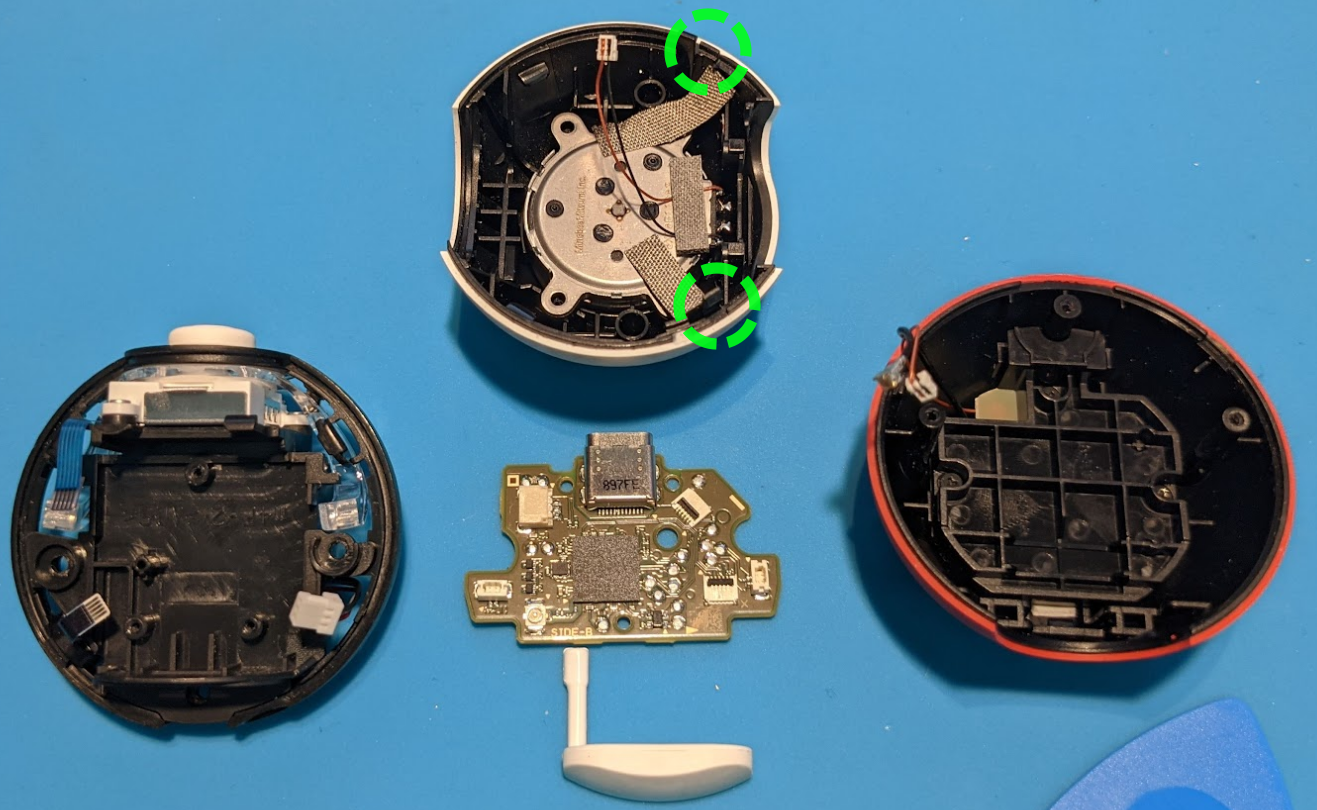
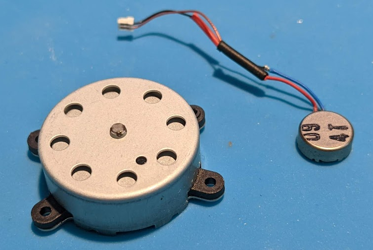
To get two auto-catching devices in one, the minimal functional needs from the above components are: the main PCB, battery, antenna, top button... and an added switch. Conveniently, the antenna and top button are the same minimal secondary PCB. A smaller vibration motor could be used, as well. I found a couple like the ones below in my stash, and they "work" though are much more subtle.
A "double pull" switch (aka two separate switches in one component) would be more compact than two discrete switches. Where to put the switch? Might as well use the opening where the joystick is, and I had some switches in my parts box from an ancient project (like... 2006) that just about fit!
I quickly identified the idea of sandwiching antenna/button PCB, battery, and main PCB on top of each other, and inspection of this approach showed that these three parts together would be just a hair below the half the height of the PokeBall Plus, if placed within the red half of the shell.
Logically, doing this twice meant I could achieve the end goal with the two red halves, and that's what I went with.
However, this brought the problem of: How do I hold the two halves together, securely? (preferably without using hot glue...) I've dropped the PokeBall plus numerous times in the past, and it's never had any issues! Preserving roughly this level of durability is a problem I idly pondered for a few weeks as I sporadically worked on other details of the project.
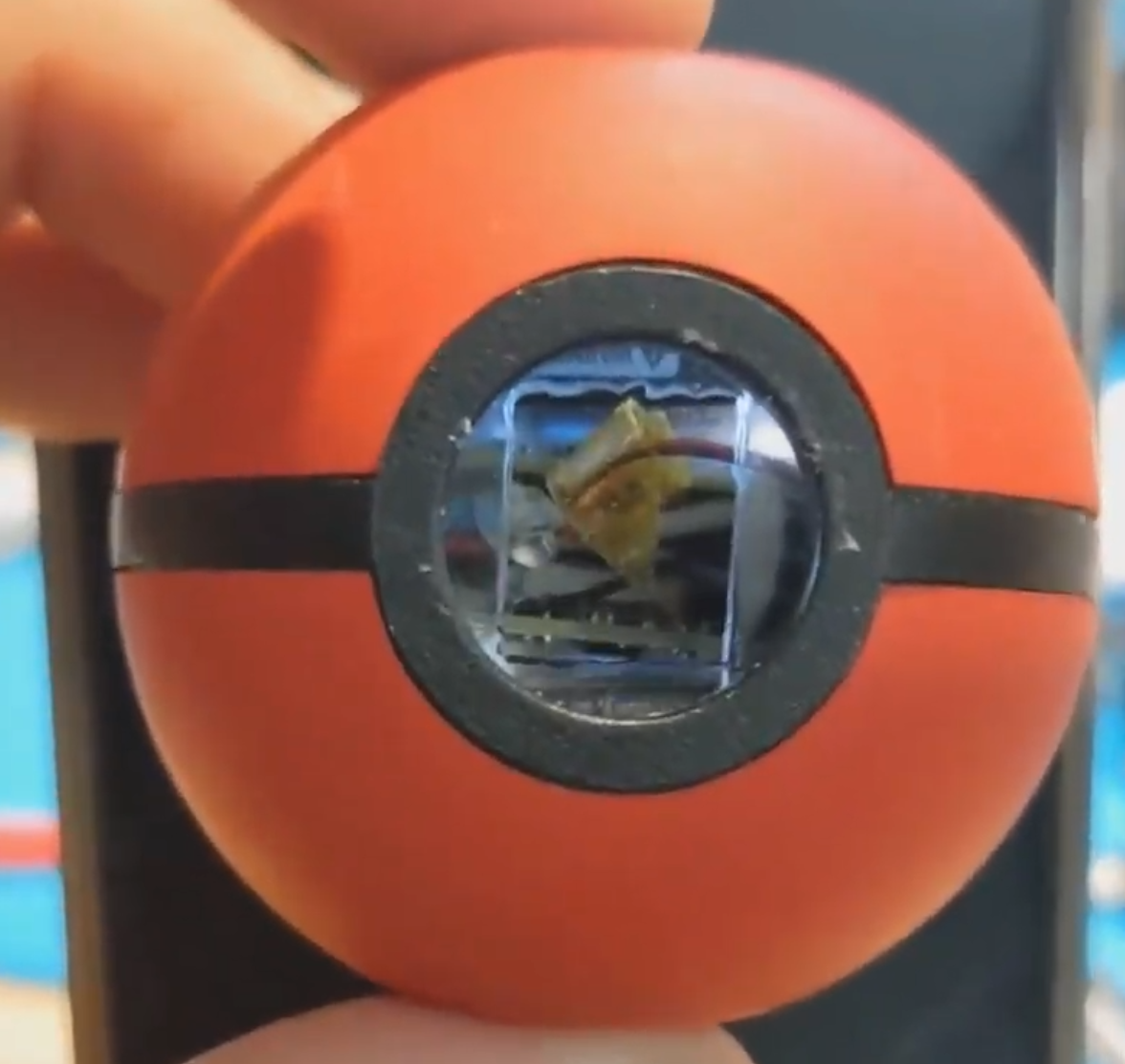
I settled finally on adding tabs on both halves that overlapped, letting me screw or pin them together. In particular, the front provided a lot of open space to achieve this. Hopefully the later pictures do a decent job illustrating this approach.
Part 3: The Build
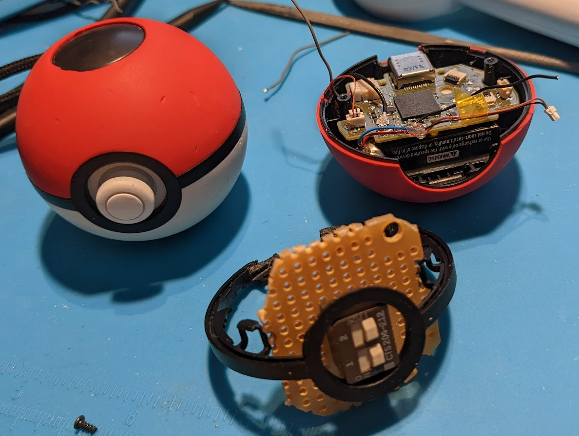
The first bit of work was to modify the middle black "ring" so that it could mate with the red shells on either side. This was pretty easy; used a dremel to add groves to the back in a few spots.
Next, I modified the double switch and its perfboard mount to fit into the ring's front opening. That combination is at the front, below:
For the on/off switch functionality, I needed additional wires, and needed to figure out where these would go. Ultimately, I traced the copper colored wire to a blob of solder on the push-button's PCB, and added another wire there. Then I soldered another wire to the ground plane, near where the antenna connector was, on the main PCB. Actually soldering these wires to the perfboard/switch was only done at the end, after all other modifications and fit-testing were done.
The most complicated part of this work was making and fitting the tabs to hold the halve together. Through lots of iteration and careful trimming, I devised a pair of polycarbonate (0.0325" thick) tabs, which I then epoxied into the red shells. There's a cutout in each for the dual switch to slide into.
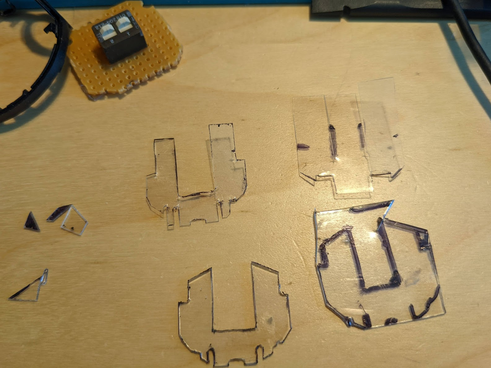
There were also a pair of improvised tabs added on the back. One has an actual M2 nut in it, because I chopped up a bracket from a Dynamixel servo...
 Peter Lyons
 Andrew Mitz
 mclien
 mulcmu