 RachelAnne
Including sounds or music in our project will always make it look and sound much more appealing. If you're working with an Arduino and have a lot of free spins, you can easily add sound effects to your project by purchasing an extra SD card module and a standard speaker. In this article, I'll show you how to play music and add sound effects with your Arduino board, as well as introduce the IC LM386 Amplifier , which we'll use in this process.
We will play the.wav music files stored on an SD card in this project. The Arduino will be programmed to read these.wav files and play the audio on a speak through an LM386 Audio amplifier.
Hardware Required
- Arduino Due Board
- 8-ohm speaker or headphones
- Arduino shield with an SD card with cs CS 4 (like the Ethernet shield)
- Components to build an external audio amplifier
- LM386 (low power audio amplifier)
- 10 kohm potentiometer
- 10 ohm resistor
- 2 x 10 µF capacitor
- 0.05 µF (or 0.1 µF) capacitor
- 250 µF capacitor
Getting Ready with Your WAV Audio Files:
The audio file to be stored on the SD card must be in.wav format and have 44100 Hz, 16-bit stereo quality. We need audio files in.wav format to play sounds from an SD card using Arduino because the Arduino Board can only play audio files in a specific format, which is wav format. There are many mp3 shields available for use with Arduino to create an Arduino mp3 player. Alternatively, to play mp3 files in Arduino, there are websites that will convert any audio file on your computer into that specific WAV file.
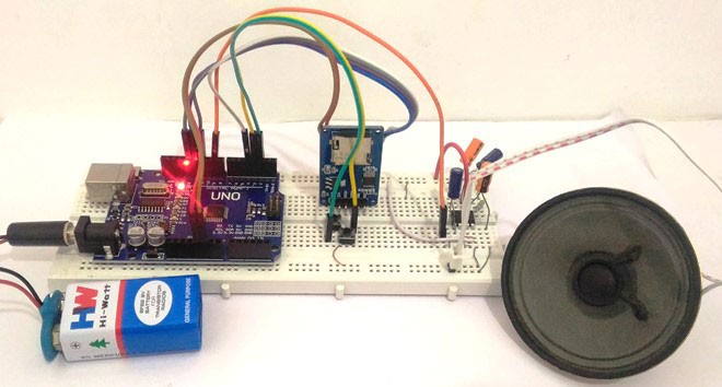
Circuit
The shield is placed on top of the Due, and a micro-SD card is inserted into the slot. The card's root directory contains a.wav file called "test.wav." For a quick test, connect a pair of headphones to the ground and DAC0 while keeping the polarity in mind.
To add a speaker to the board, connect an amplification circuit between the DAC0 pin and the speaker. The amplification circuit will boost the speaker's volume, There are numerous audio amplifiers available, with the LM386 being one of the most common. The following scheme demonstrates how to construct the circuit using the LM386 and a variety of components. You can power the LM386 by connecting the Vs pin to various voltage sources, such as the +5 V on the Arduino Due's 5V pin or an external 9V battery, The capacitor is connected to pins 1 and 8 of the LM386 provides the amplifier's gain. The gain is set to 200 with the 10 F capacitor, and 50 without the capacitor. The volume of the amplifier can be adjusted using the potentiometer.
Caution: Do not connect the speaker directly to the Arduino Due's pins.
Code
/*
Modified on Dec 15, 2020
Modified by Harold Bradshaw from Kynix Blog Examples
Home
*/
// CONNECTIONS:
// DS1302 CLK/SCLK --> 5
// DS1302 DAT/IO --> 4
// DS1302 RST/CE --> 2
// DS1302 VCC --> 3.3v - 5v
// DS1302 GND --> GND
#include <ThreeWire.h>
#include <RtcDS1302.h>
ThreeWire myWire(6,7,8); // IO, SCLK, CE
RtcDS1302<ThreeWire> Rtc(myWire);
void setup () {
Serial.begin(57600);
Serial.print("compiled: ");
Serial.print(__DATE__);
Serial.println(__TIME__);
Rtc.Begin();
RtcDateTime compiled = RtcDateTime(__DATE__, __TIME__);
printDateTime(compiled);
Serial.println();
if (!Rtc.IsDateTimeValid()) {
// Common Causes: 1) first time you ran and the device wasn't running yet 2) the battery on the device is low or even missing
Serial.println("RTC lost confidence in the DateTime!");
Rtc.SetDateTime(compiled);
}
if (Rtc.GetIsWriteProtected()) {
Serial.println("RTC was write protected, enabling writing now");
Rtc.SetIsWriteProtected(false);
}
if (!Rtc.GetIsRunning())...
Read more »
 Lithium ION
 electronicsworkshops
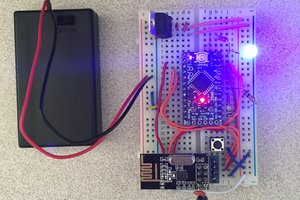
 Noah Thurston