Subhajit
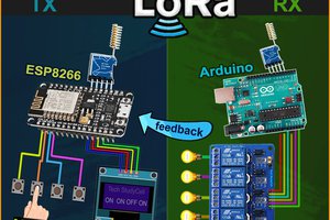
In this Lora IoT project tutorial, I have shown how to make the LoRa Arduino ESP8266 control relay from the Blynk IoT platform with real-time feedback.

In this article, I have covered the following topics.
- Explained this ESP8266 Arduino Lora IoT-based home automation project.
- Explained Transmitter & Receiver Lora circuit.
- Setup Blynk cloud account for the ESP8266.
- Explained the source codes for this LoRA IoT project.
- Control high voltage appliances with LoRa.
Tutorial Video on the LoRa IoT Project with Blynk
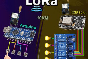
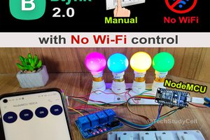
So if you follow all the steps, you can easily make this Lora IoT project, to control any appliances from anywhere in the world with the combination of LoRa and Wi-Fi. So this project is very useful in rural areas where WiFi is not available.
Although the PCB is not mandatory, I have used PCB for the transmitter LoRa circuit to make the circuit compact and give the project a professional look.
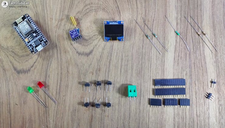
Required components for the Transmitter Lora circuit:
- Lora Module REYAX RYLR998 1no
- ESP8266 NodeMCU 1no
- 1k Resistors 2no
- 4.7k Resistor 1no
- 10k Resistor 1no
- 5-mm LED 2no
- Push-button 4no
Required components for the Receiver Arduino Lora circuit:
- Lora Module REYAX RYLR998 1no
- Arduino UNO 1no
- 5v 4-channel Relay Module 1no
- 4.7k Resistor 1no
- 10k Resistor 1no
- 5-mm LED 1no
Required Components for the PCB used for transmitter circuit:
- REYAX RYLR998 or RYLR896 Lora module 1no
- ESP8266 NodeMCU 1no
- 1k Resistors 2no
- 4.7k Resistor 1no
- 10k Resistor 2no
- 5-mm LED 2no
- Push-button 6no
- Jumper 2no
- Terminal connector 2 pin 1no
- OLED (optional)
How does this LoRa IoT Project Works?

For controlling the appliances from the smartphone, I used the Blynk IoT app.
This LoRa Wi-Fi system works in the following steps:
- When you press any button in the Blynk IoT app, the signal is sent to the Blynk Cloud.
- Through the internet, the ESP8266 NodeMCU receives the signal from the Blynk cloud.
- Afterwards, the ESP8266 sends the same signal through LoRa to Arduino.
- After receiving the signal through LoRa, Arduino turns ON/OFF related relay and sends the feedback to ESP8266 through the LoRa module.
- The ESP8266 will turn on the status LED and send the feedback to Blynk cloud once it receives feedback.
- Using the Blynk IoT app, you can also monitor real-time feedback.
Transmitter Lora Circuit Using NodeMCU ESP8266
![]()
In the transmitter LoRa circuit, I have used NodeMCU. I have made a voltage divider using 4.7k and 10k resistors to drop down the 5volt logic level to 3.3volt logic level for the LoRa module.
I have used D7 as RX and D8 as TX for the serial communication with the LoRa module.
The pushbuttons are connected with the SD3, D3, D5, and RX GPIO pins of NodeMCU.
The status LED is connected with the D4 GPIO pin.
You can use any 5V DC power supply to supply the circuit.
Receiver Lora Circuit Using Arduino UNO
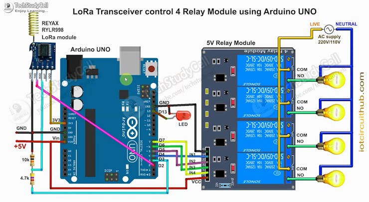
On the receiving end, I have used Arduino UNO. In the circuit, I have made a voltage divider using 4.7k and 10k resistors to drop down the 5volt logic level to 3.3volt logic level.
I have used D4, D5, D6 & D7 pins to control the 4-channel relay module.
As per the source code, when the control pins of the relay module receive the LOW signal the respective relay will turn on and the relay will turn off for the HIGH signal in the control pin.
I have used a 5V 2Amp power supply to supply the Arduino UNO and relay module.
Please take the proper safety precautions while working with high voltage.
Create New Template for ESP8266 in Blynk Cloud
For this smart house project, I have used the Blynk IoT Cloud Free plan. Click on the following link to create a Blynk Cloud account.
https://blynk.cloud/dashboard/register
Steps to Create New Template for ESP8266
- Click on New Template.
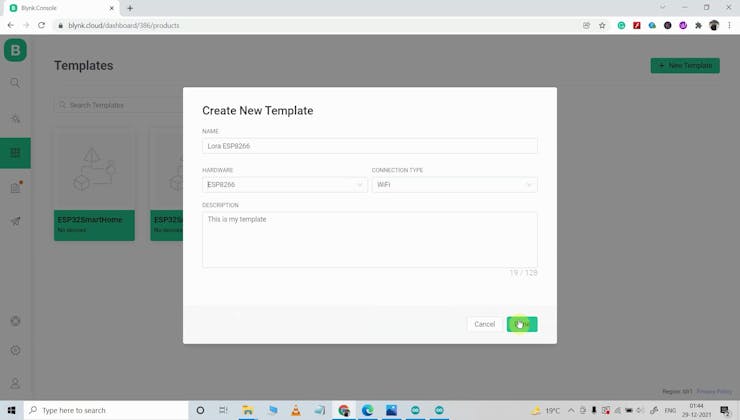
- Enter a template name, select the hardware...