Goal of this project was to create a 7V/10A power supply for a big 74-series logic project (which never happened...)
I decided to use as much compoments manufactured in my home town by Tesla Rožnov in former Czechoslovakia prior to 1990, as possible.
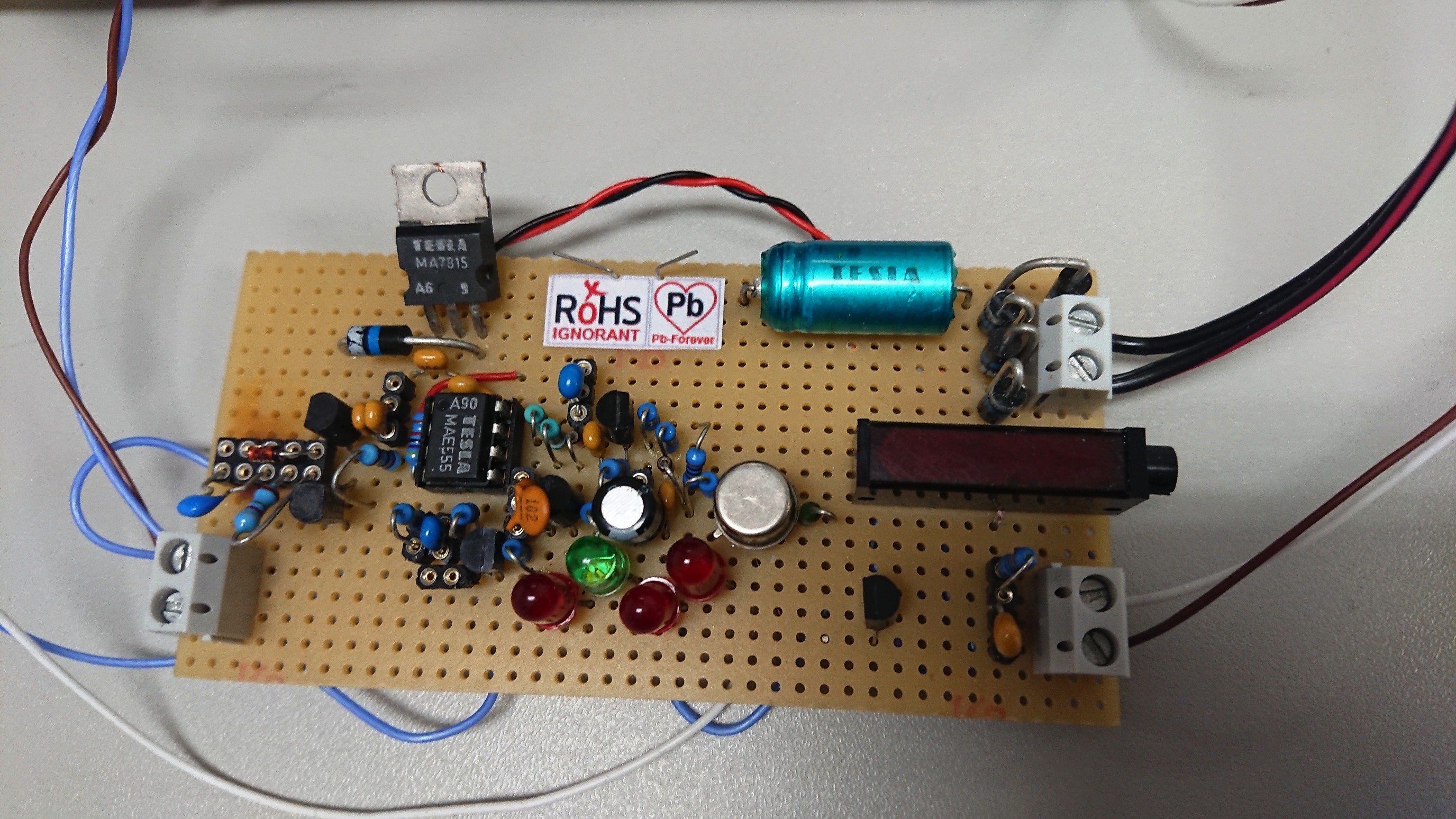
The power supply is constructed on three PCBs - power board, gate-drive board and control board.
Power board is hand-made by cutting and dremelling (grinding). A universal PCBs were used for control board and gate-drive board.
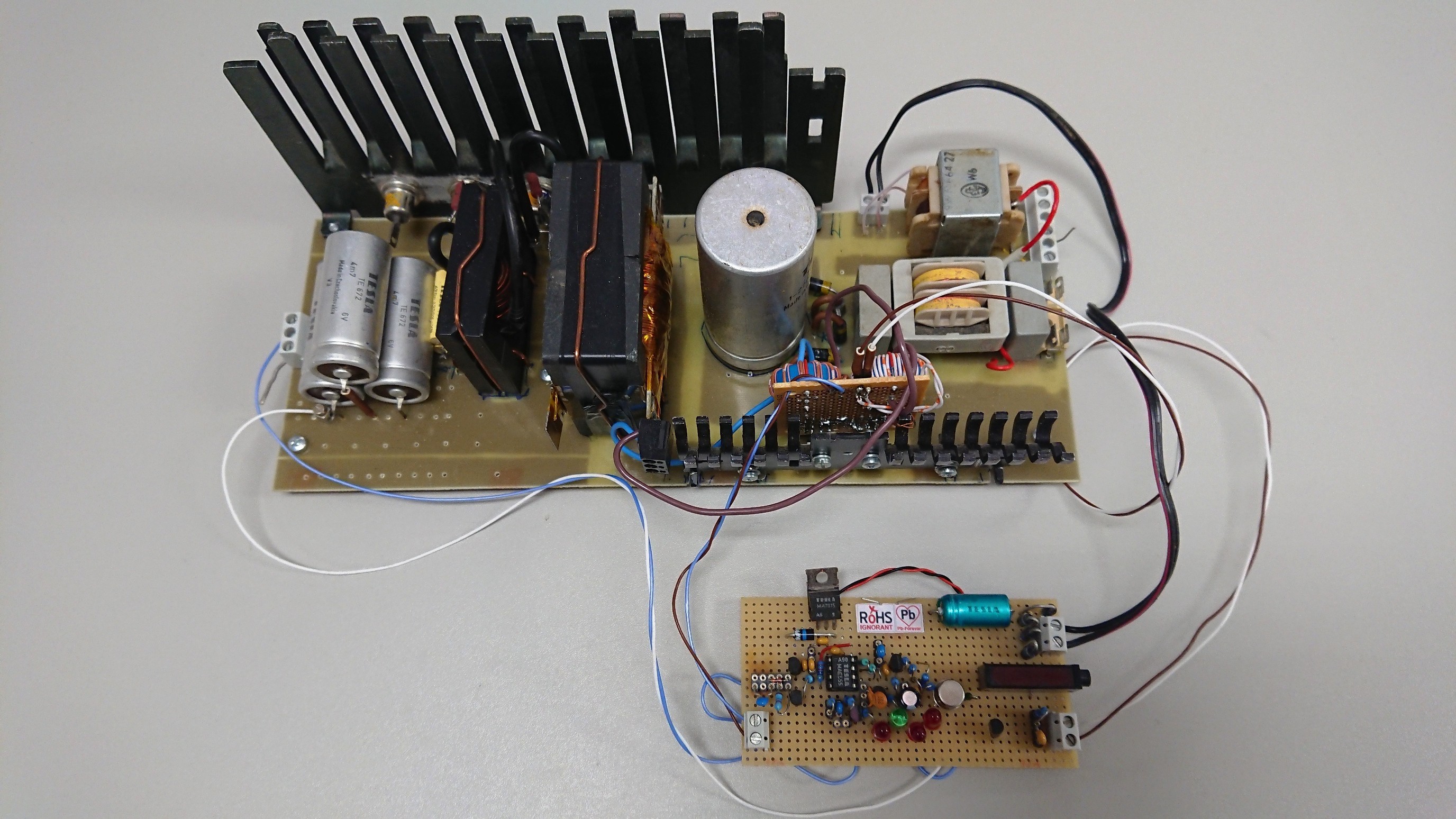
AC input 230V is 3-wire, with Protected Earth connected to output GND for safety.
The converter uses a two-switch forward topology, which is simple to control and reliable, just needs to keep duty cycle below 50%.
Control circuit is on the secondary side for safety and to avoid the need for an optocoupler. Each magnetic component adds wow factor, so this converter contains 6 of them - iron transformer for supplying the control board, EMI choke from an old CRT TV, gate drive transformer, current sense tranformer, main transformer, and output inductor.
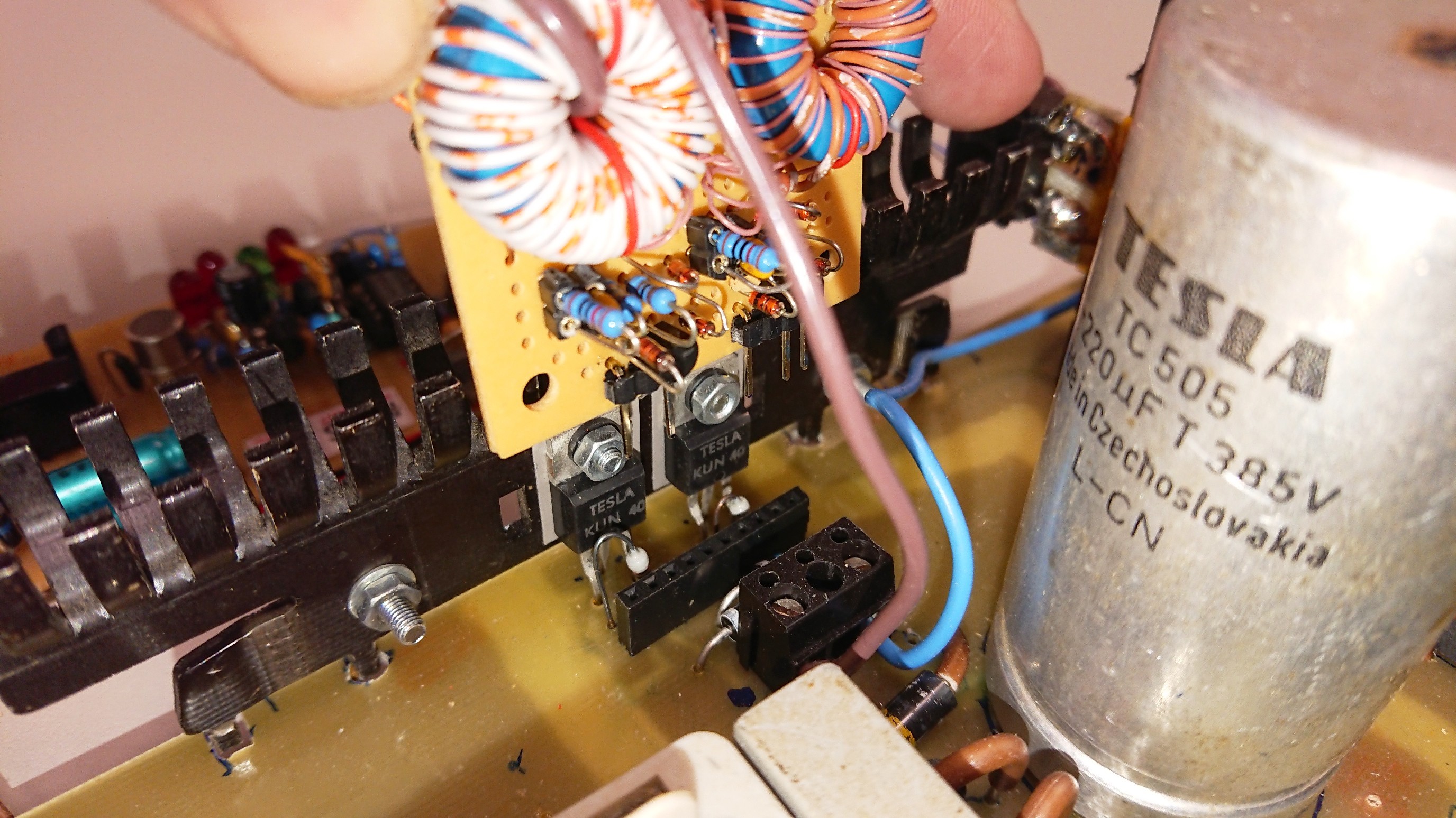
Attached is simulation schematic of the control part. Power stage schematic is similar to Danyk's welding inverter supply (http://danyk.cz/svar_en.html).
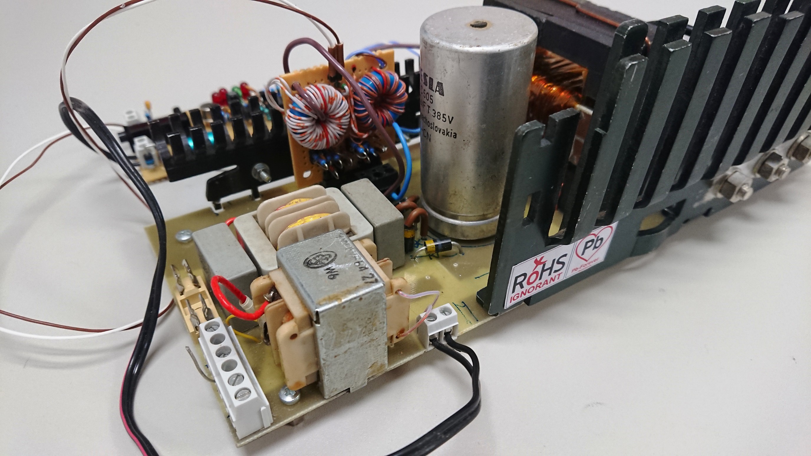
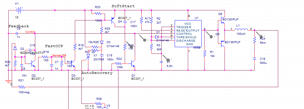
Bulk capacitor is Tesla TC505 - 220uF/385V.
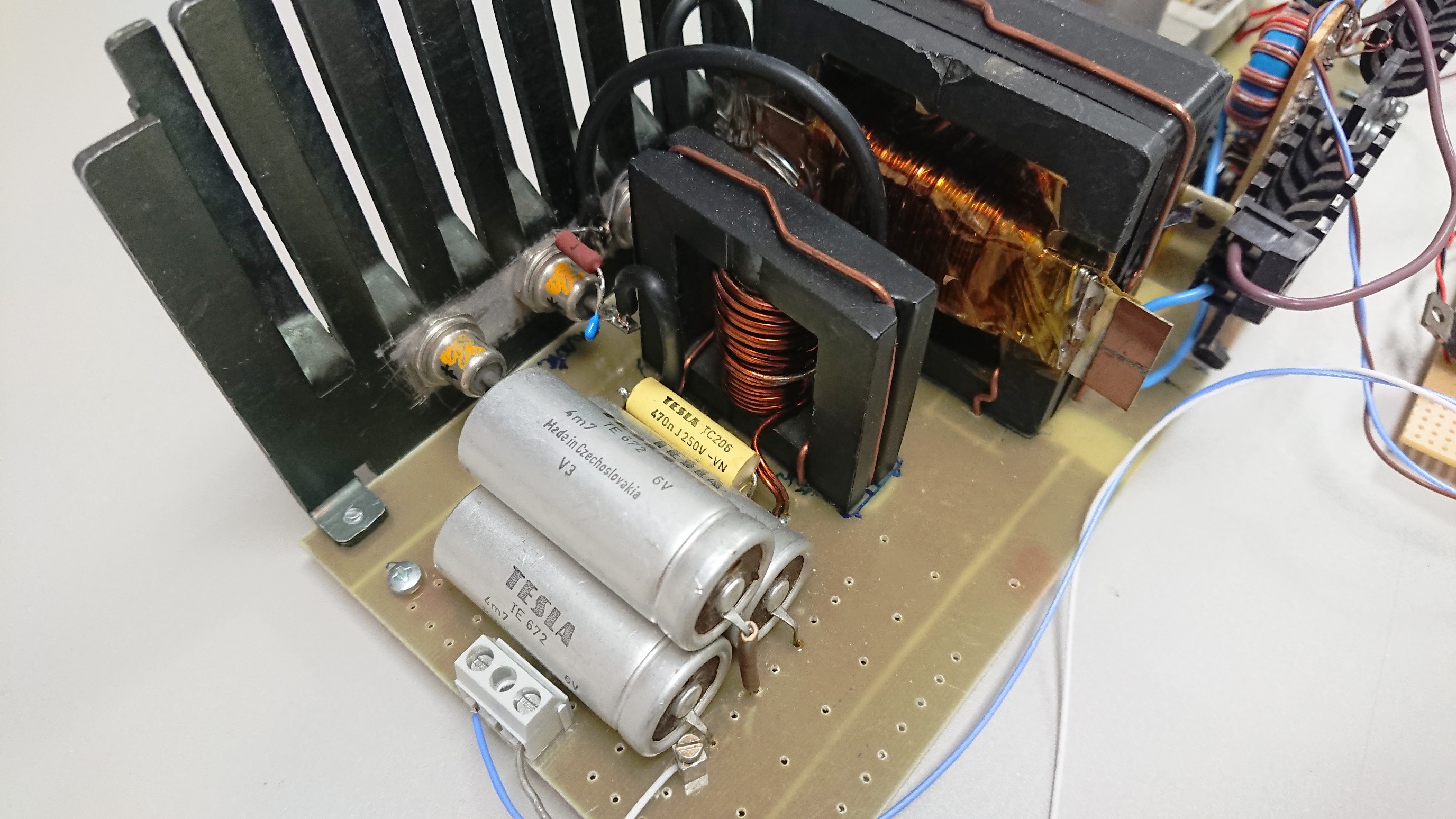
MOSFETs are Tesla KUN40 - 400V, 1Ohm, mounted on heatsink, which turned out unnecessary. Diodes on the primary side are Tesla KY197 - breakdown voltage specified at 200V, measured at >1100V.
Below: detail of primary side components:
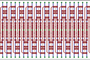
The main tranformer uses an overkill E65 ferrite core found in a drawer. Core former was not available, so it had to be hand-made from FR4, integrated with a planar secondary winding 8-).
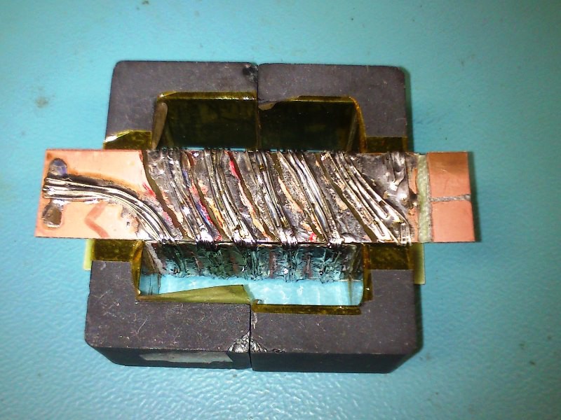
Secondary winding is 5 turns, primary is 50 turns, isolated by several layers of kapton tape. Primary inductance is 12.4mH.
Output inductor (92uH) is constructed on gapped ETD49 core and is barely adequate - saturates at about 11 or 12 Amps of output current.
Diodes on the secondary side are Tesla KYW31/150, military grade marked by crossed swords, mounted on a heatsink obtained from the CRT TV too.
Output capacitors are 3pcs Tesla TE672 - 4.7mF/6V. Originally five of these were used in a 5V/60A power supply produced by ZPA Košíře. I didn't have any more suitable capacitors, and using them below rated voltage is too mainstream, so these were carefully "formed" using lab power supply, settling to few tens of microamps leakage at 8.5V. Measured total capacitance was an impressive 19.4mF, ESR was not measured.
Below: detail of the secondary side components.
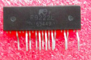
The converter is controlled by the famous NE555 timer.
This IC is famous, old, and it was also manufactured by Tesla Rožnov (MAE555), so there are plenty of reasons to use it for control of switching-mode power supply :-)
Schematic of the control part:
Switching frequency of 30kHz and maximum duty cycle of 45% is set by components R2,R3,C1,D1. Output voltage is regulated to about 7.2V. 4 LEDs are connected in series, at this voltage they start to conduct, Control voltage (pin 5 of the 555) is pulled lower via Q2 and duty cycle is decreased. Supply for the control board is 15V, stabilized by Tesla MA7815. Range of Control voltage is therefore 0 to 10V. Characteristics of duty cycle and frequency vs. Control voltage are attached below. After plugging-in, there is soft-start consisting of Q1, C17, R15, R22. Control voltage starts from zero and ramps up in about 50ms.
Overcurrent protection uses a current sense transformer. Its output voltage is filtered and connected to base of Q3. When it exceeds ~0.55V, Q3 conducts and lowers Control voltage via Q4 and Q1.
Output of the 555 is strengthened by a push-pull transistors and fed into gate-drive transformer. Gate-drive transformer with trifilar windings is located on the third PCB near the MOSFETs, together with current sense tranformer.
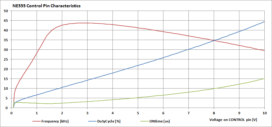
During no-load the switching frequncy falls down to 6.5kHz, so it acoustically indicates too-low load. With...
Read more »
 engineerkid1
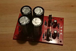
 Hamza Deniz Yılmaz
I loved the RoHS ignorant logo. Long live to Pb!
Greetings from Mexico.
#EFHC