 Richard Nock
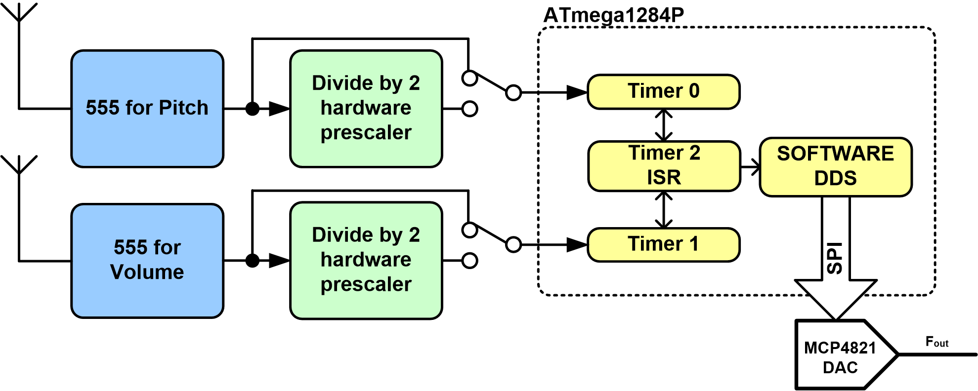
The Theremin has two 'antennas', of which are used to control the pitch and volume of the produced tone. To detect the distance of the user’s hand from an antenna, the venerable 555 timer is used in an astable mode. The user’s hand changes the effective capacitance in the astable circuit, changing the frequency at which the 555 oscillates at. The 555 circuit is from the ThereminVision-II project by Terry Fritz. Originally, he used these 555 circuits to detect obstacles, people and other robots on his own robotic platforms.
A 7476 is used to divide the 555’s output frequency by 2 if needed, as it is easy to experience 8-bit timer overflow. The output from the 555/7476 is then used to clock a timer in the ATMega1284p microcontroller. The ATmgea1284p microcontroller measures the frequency of the 555’s with no hands present on start-up or when the calibrate button is pressed, as each 555 circuit will oscillate at its own particular frequency, dependent upon component values and objects around its antenna.
Timer 2 is used in the output compare mode to generate a periodic interrupt. This is used to read the contents of Timer 0 and Timer 1 (measuring the frequency) and the absolute frequency change from the calibration frequency. This allows for the small frequency changes from the 555’s natural oscillation frequency to be easily measured.
The changes in 555’s frequencies are then used to change the output frequency and amplitude. To achieve the waveform generation, a software based DDS (direct digital synthesizer) is used in conjunction with a MCP4821 SPI 12-bit DAC.
A video discussing the build and a poor demonstration:
I plan on developing this project further with a PCB. In particular, the audio output stage needs significant work to improve audio quality.
Code will be released for this prototype once it has been tidied up!
 jr9910
 Sagar 001
 Scott
Scott
 Techmeology