Current Status: Dissection and Reassembly of Separate Prompt Files possible
Not yet Possible: Changing Internal Flash image parts. DFU is signed. Time to find a way via hardmod.
Trying to understand the code and getting sidetracked by the Prompts
Already have an account? Log in.
To make the experience fit your profile, pick a username and tell us what interests you.
Current Status: Dissection and Reassembly of Separate Prompt Files possible
Not yet Possible: Changing Internal Flash image parts. DFU is signed. Time to find a way via hardmod.
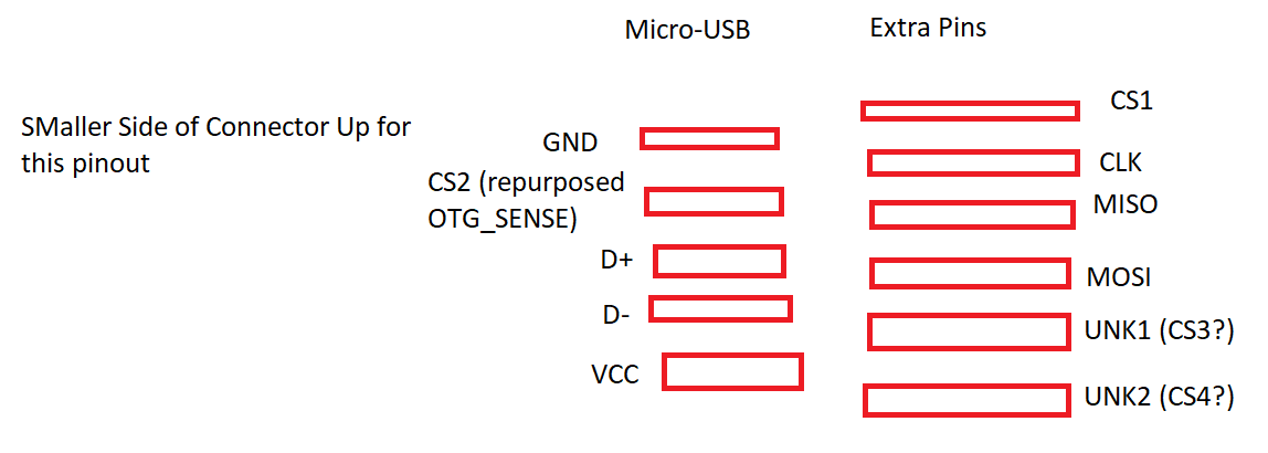
Adaptor pinout figured out. Messing with the firmware now possible without opening up.
Debug Port uses the same plug as the Samsug Galaxy S3 used for its MHL extra pins. Need to make me a adaptor based on a MHL adaptor and some soldering
Uploaded a newer version of my utility that got flashdump and jailbreak shorthands for getting a different key inserted for self-signed DFU files.
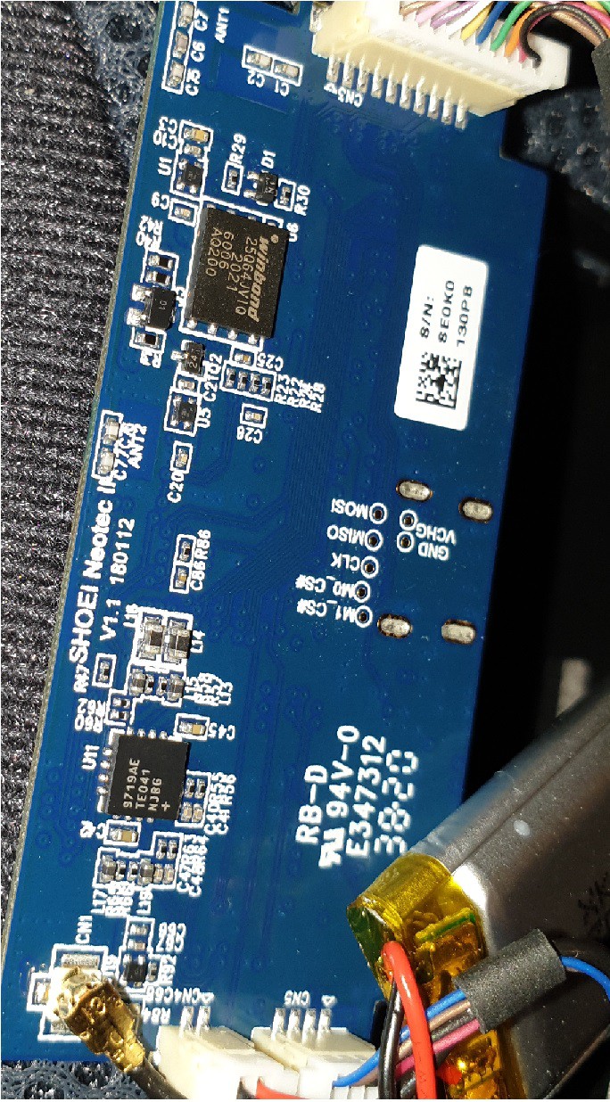
SPI works for yanking off a flash dump. (that means that the port is not locked at all) Pins on the chip for tracking down the SPI are following: Left side: 3rd from bottom: CS 4th from, bottom: MISO 5th from bottom: MOSI 6th from bottom: CLK Noticed that they are wired out on a undocumented extra set of Pins in the micro-USB connector.
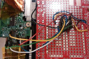
Waiting for a CSR USB-SPI Programmer since the SRL2 got a obvious SPI Port.
(the 10S only got TP1-TP10 and no meaningful names)
SRL2 is my main helmet intercom, thats why i dont want to mess much with its firmware. Got to find out which chipset pins are the SPI ones to rigg a connection jig for the 10S which i bought for development/reverseing
Peeking into the Hardware (disassembling the SRL2 main unit is really easy since its only 4 screws holding it together) helped me finding out it being a CSR device.
Understanding the outer firmware file format was easy after spotting the pattern in the header. Each file inside is MD5-summed and stored with offset and length in the header.
Split Layout Headsets got a DFU file for the internal flash and a vp.bin for the external flash. Only those can be modified so far since (found out later) the external flash is not signature-checked.
Extraction of the external IMG is possible with the ADK toolkits since its a Filesystem image in their format.
Current workflows are written into the linked Github code


 darth_llamah
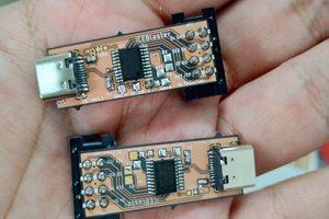
 TinLethax
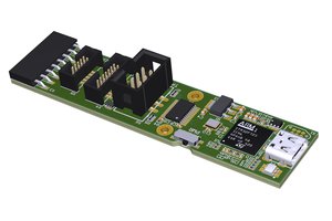
 Florian Baumgartner
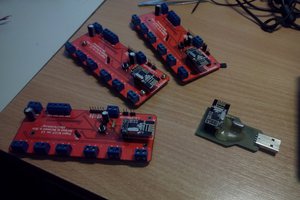
 Necromant