 Bharbour
When I started this project, I wanted something very simple and inexpensive. I thought about some kind of microcontroller based project, but that idea failed both the simple and the inexpensive goals. Same with a discrete logic system. A simple battery (9V) powered voltage divider, with taps spaced about 1V apart with each tap applied to a pin on the RJ-45 connector meets the requirements. There are 2 boards for this tester, a "sender" and a "receiver".

Both boards are built on identical PCBs which is convenient since OSHPark returns 3 PCBs on a minumum order. An RJ-45 connector and 8 test points go onto both the "sender" and the "receiver" boards. The "sender" board also gets 9 1K Ohm resistors and a battery holder for a 9V battery glued to the back side.

The RJ-45 connector and the test points are all that go onto the "receiver" board.

I thought about putting a voltage regulator on the "sender" board so that the voltages on each pin would be closer to the pin number, but decided the slight ambiguity was better than the fragility that would come with adding an LDO voltage regulator. A simple 3 pin jumper is used as a power switch on the "sender" board.

Each of the test points on the boards corresponds to a pin on the RJ-45 connector.
To use these critters, you will need a handheld voltmeter.
- Make certain that both ends of the cable being tested are disconnected from the router and the computer!
- Plug one end of the CAT5 cable into the sender board.
- Turn the "sender" board on by placing the jumper block across the "ON" and the center pin on the 3 pin jumper.
- With your meter - probe connected to TP1 on the "Sender" board, test the voltages on TP2 through TP8. The voltages should resemble the test point number ie, TP2 should be about 2V and TP3 about 3V. If any of the test point voltages are identical to the voltage on another test point, there is a short circuit in the cable. Also, a short circuit between pins will throw all the test point voltages off their approximation of the pin number.
- If all of the test point voltages on the "sender" board look good, connect the "receiver" board to the other end of the CAT5 cable.
- With your meter - probe on TP1 of the "receiver" board, test the voltages on TP2 through TP8 on the "receiver" board. Voltages seen on the "receiver" end should match the voltages seen on the "sender" end pretty closely. Any test points showing 0 or very low voltages will indicate an open circuit on the cable, most likely in one of the connectors. If the measured voltage on a test point does not resemble the test point number, there are wires interchanged in one of the connectors.
- When all voltages look correct, turn the "sender" board off by moving the jumper block to the "OFF" pin or the battery will run down.
My board was built with 5% tolerance resistors. With a fresh 9V battery showing 9.32V, the test point voltages with respect to TP1 are:
- TP2 2.08V
- TP3 3.13V
- TP4 4.18V
- TP5 5.23V
- TP6 6.28V
- TP7 7.34V
- TP8 8.39V
The PCB is published under the BSD license. If it is re-published, please include the BSD license text that is in the file description.


 Tim Savage
 c00
c00
 kp
kp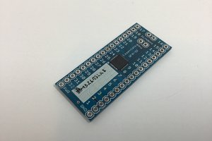
 Ben Lim
9V for operation? Now you got me trying to make it run on 5V or 3V