 deʃhipu
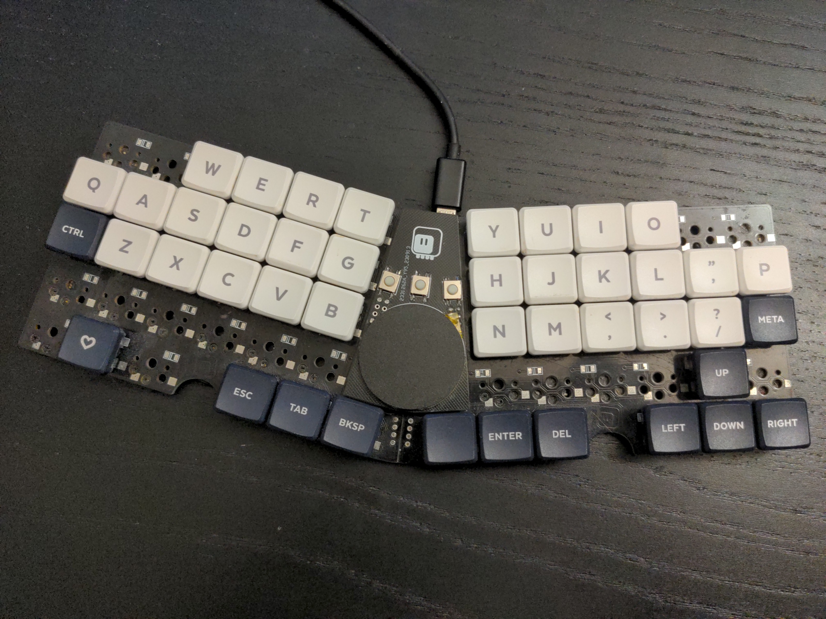
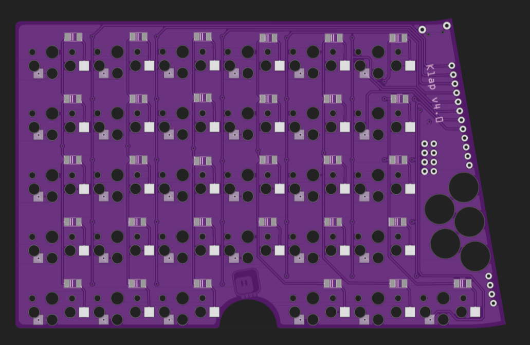
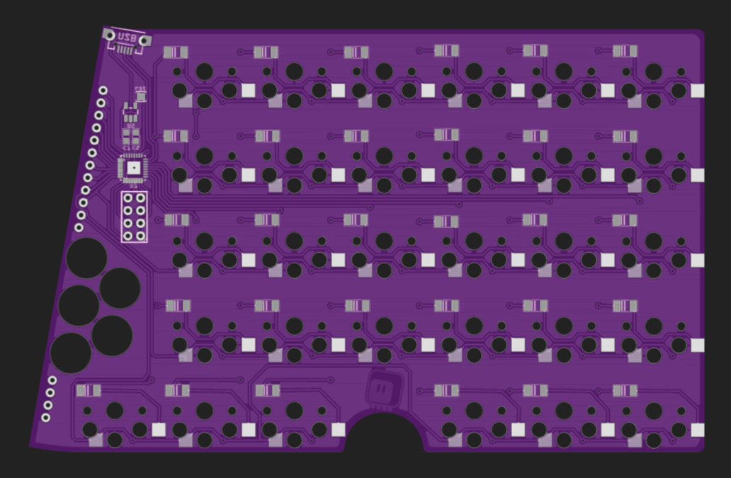
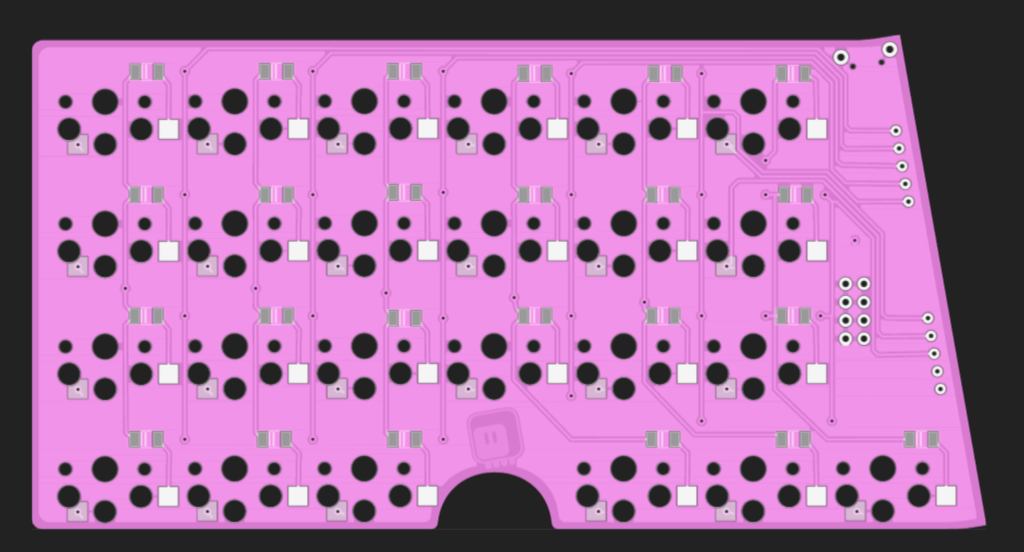
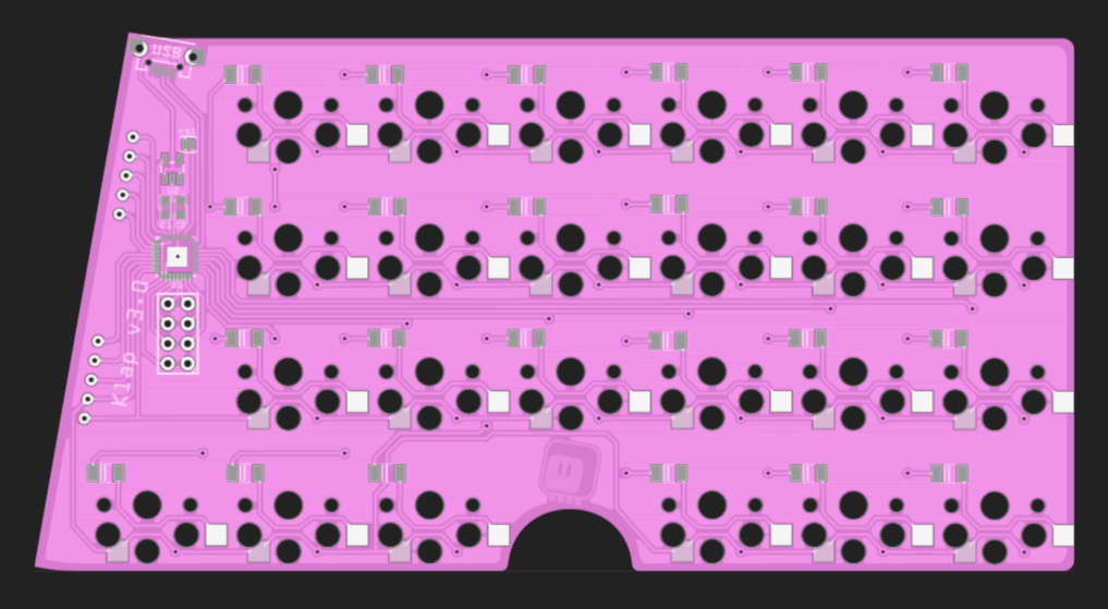
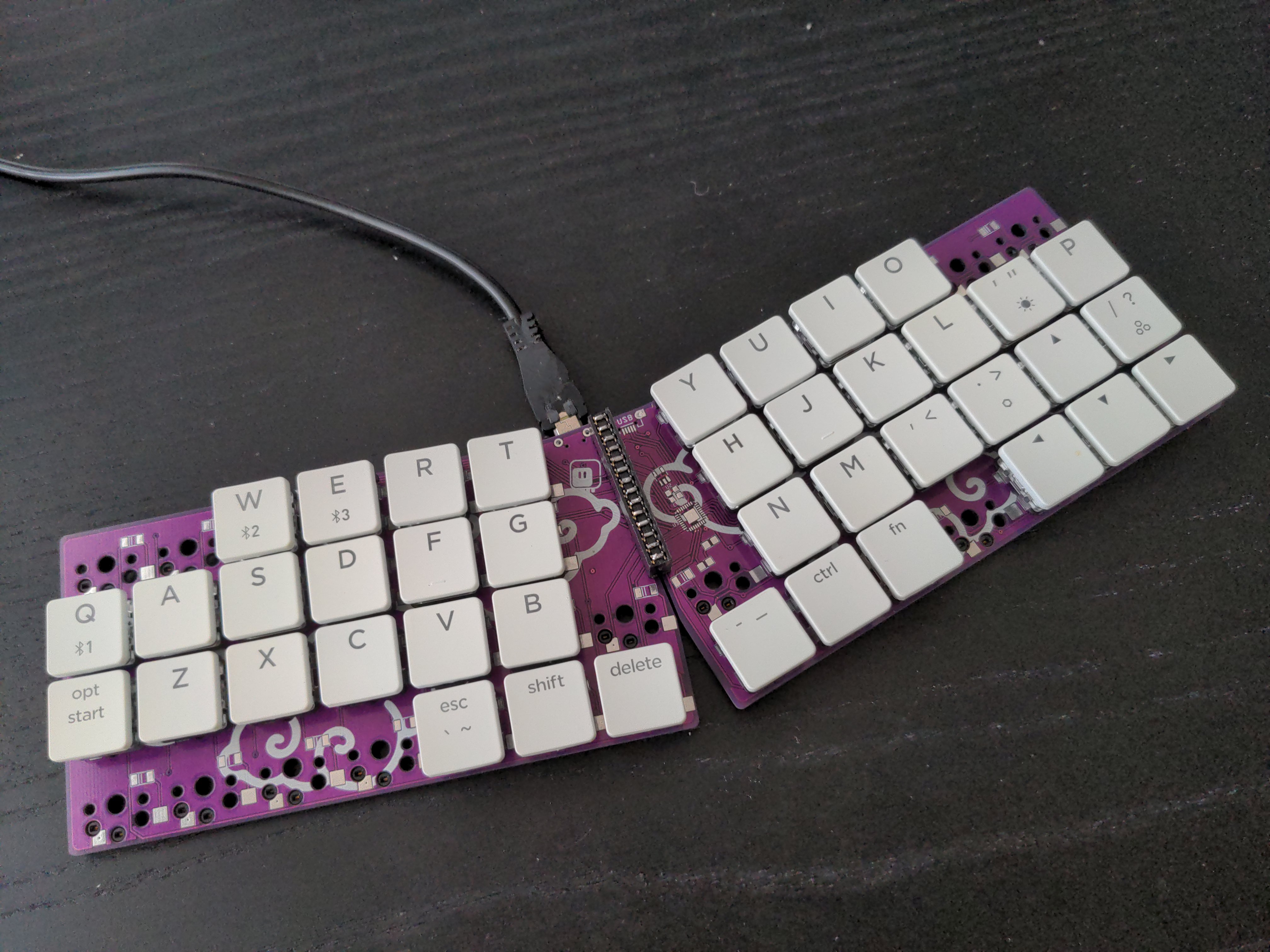
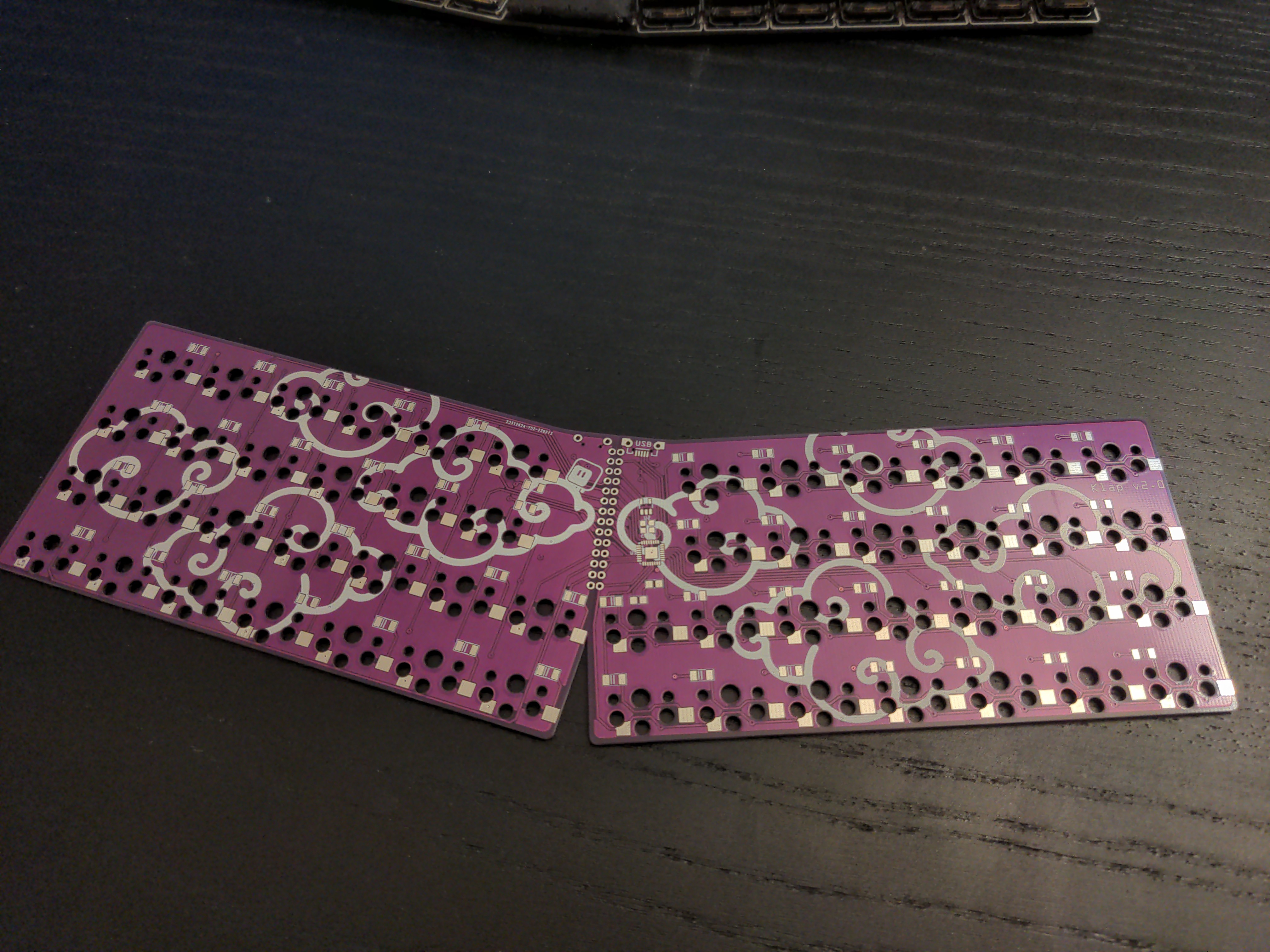
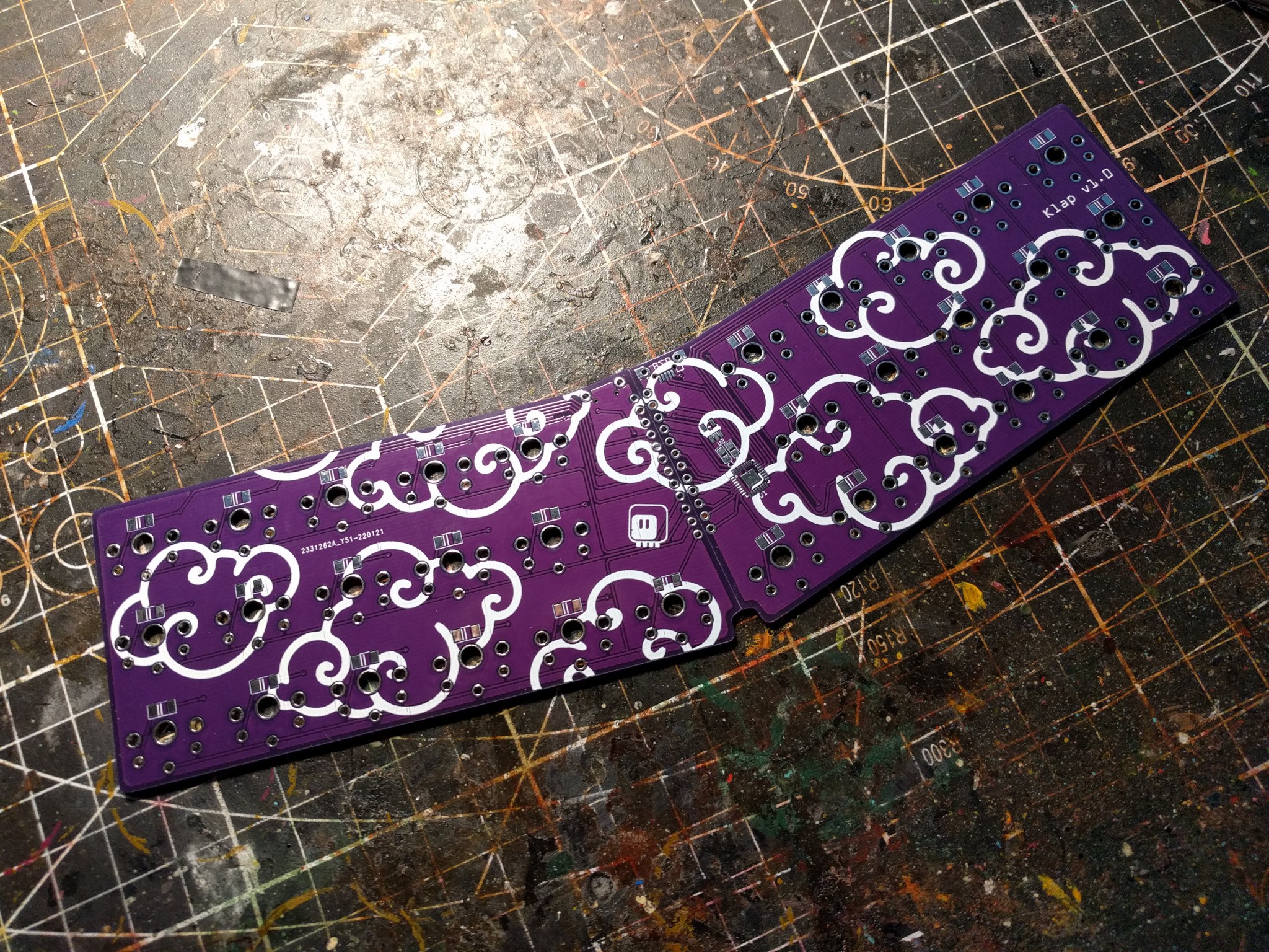
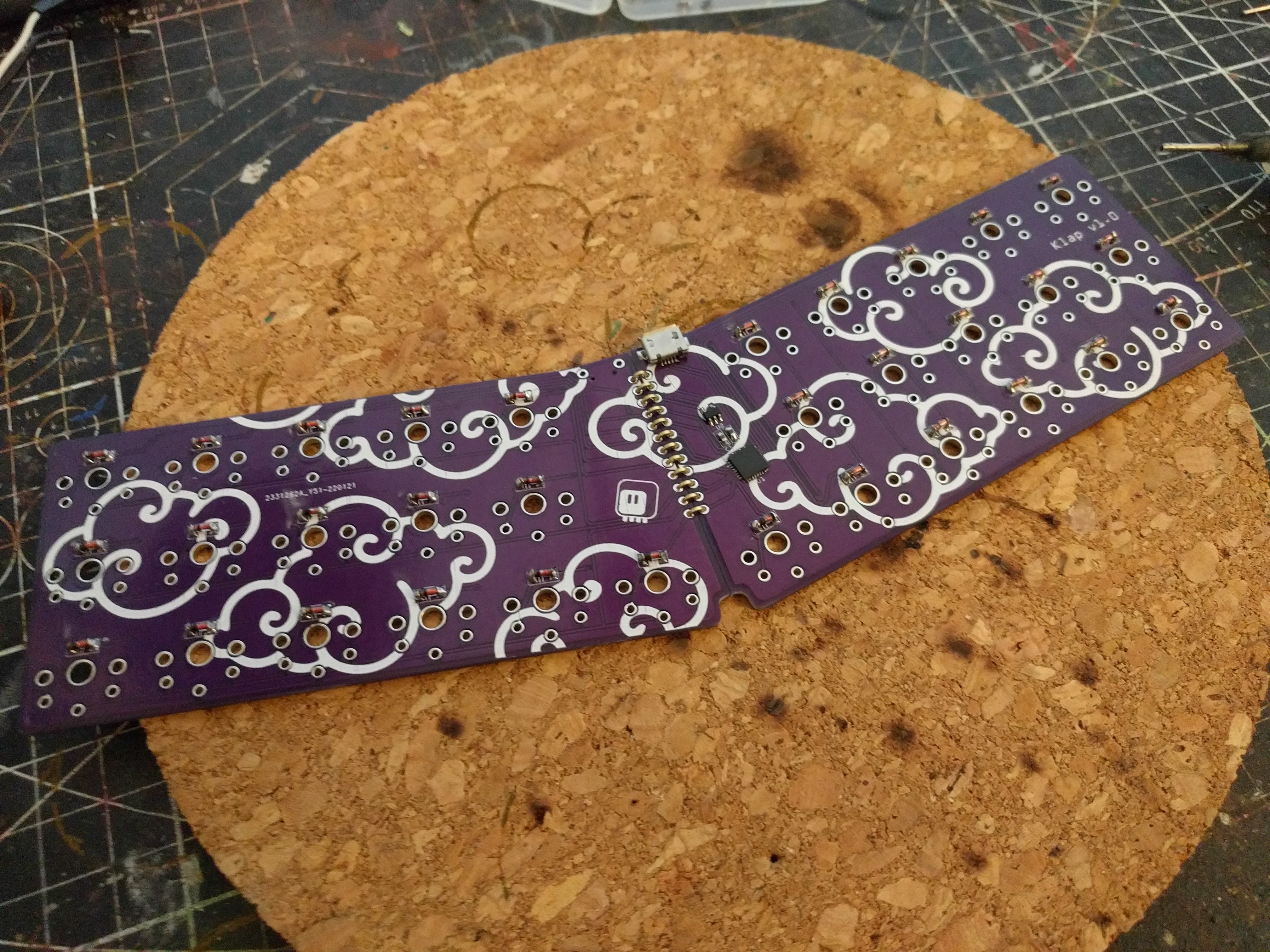
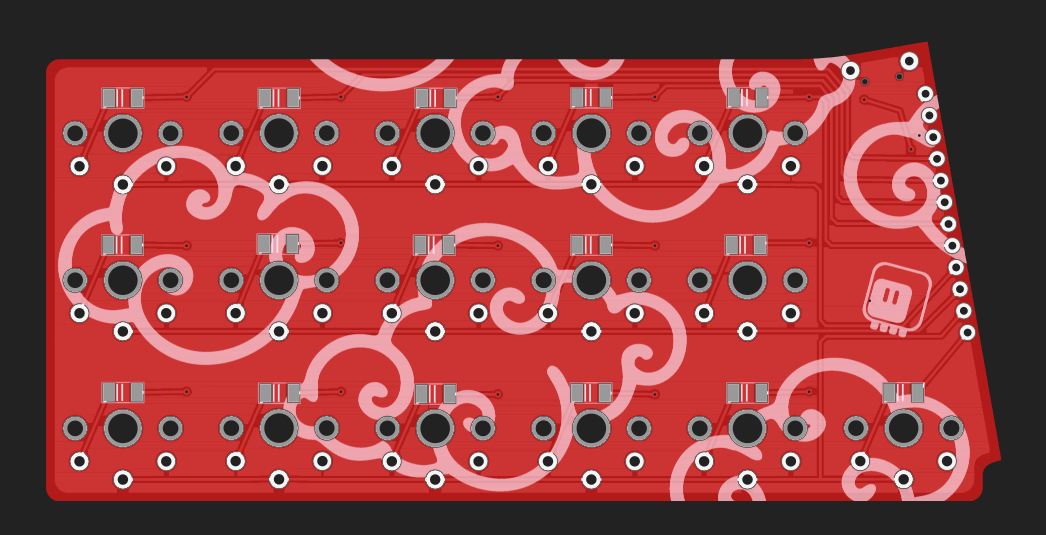
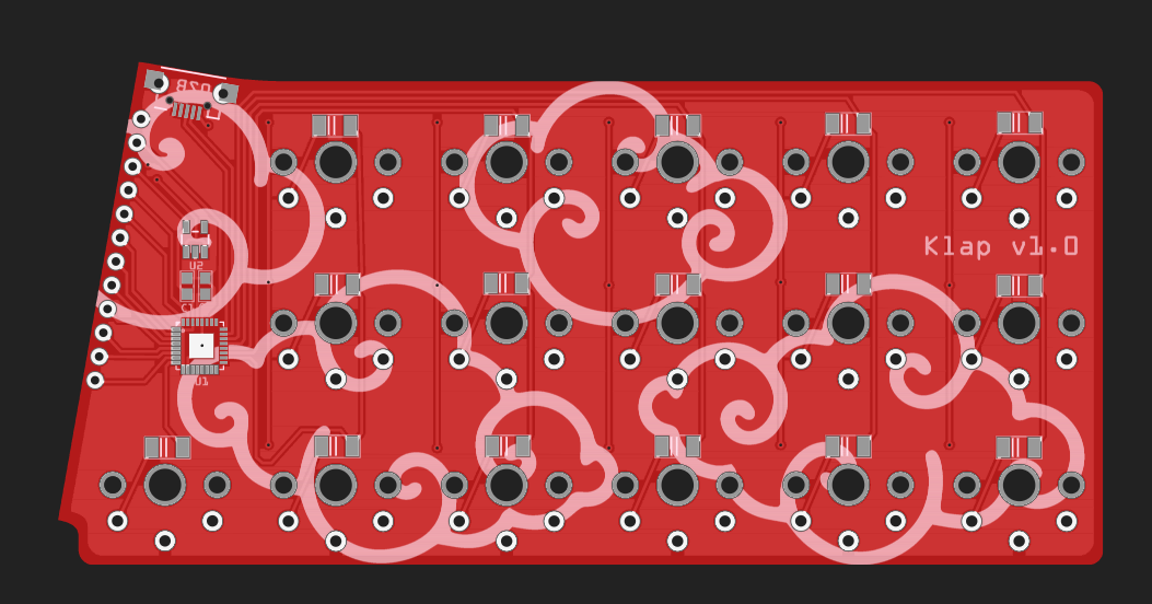
This is a small, unibody-split keyboard with 32 keys in a very compact layout. It was inspired by Ben Vallack's "Card" keyboard, but is wired and runs on CircuitPython.
0%
0%
Klap Keyboard
Is that a keyboard in your pocket?
Become a Hackaday.io member
Already have an account? Log in.
Just one more thing
To make the experience fit your profile, pick a username and tell us what interests you.
Pick an awesome username
hackaday.io/
Your profile's URL: hackaday.io/username. Max 25 alphanumeric characters.
Pick a few interests
Projects that share your interests
People that share your interests


 RasmusB
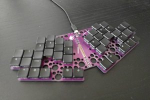
 Simon Merrett
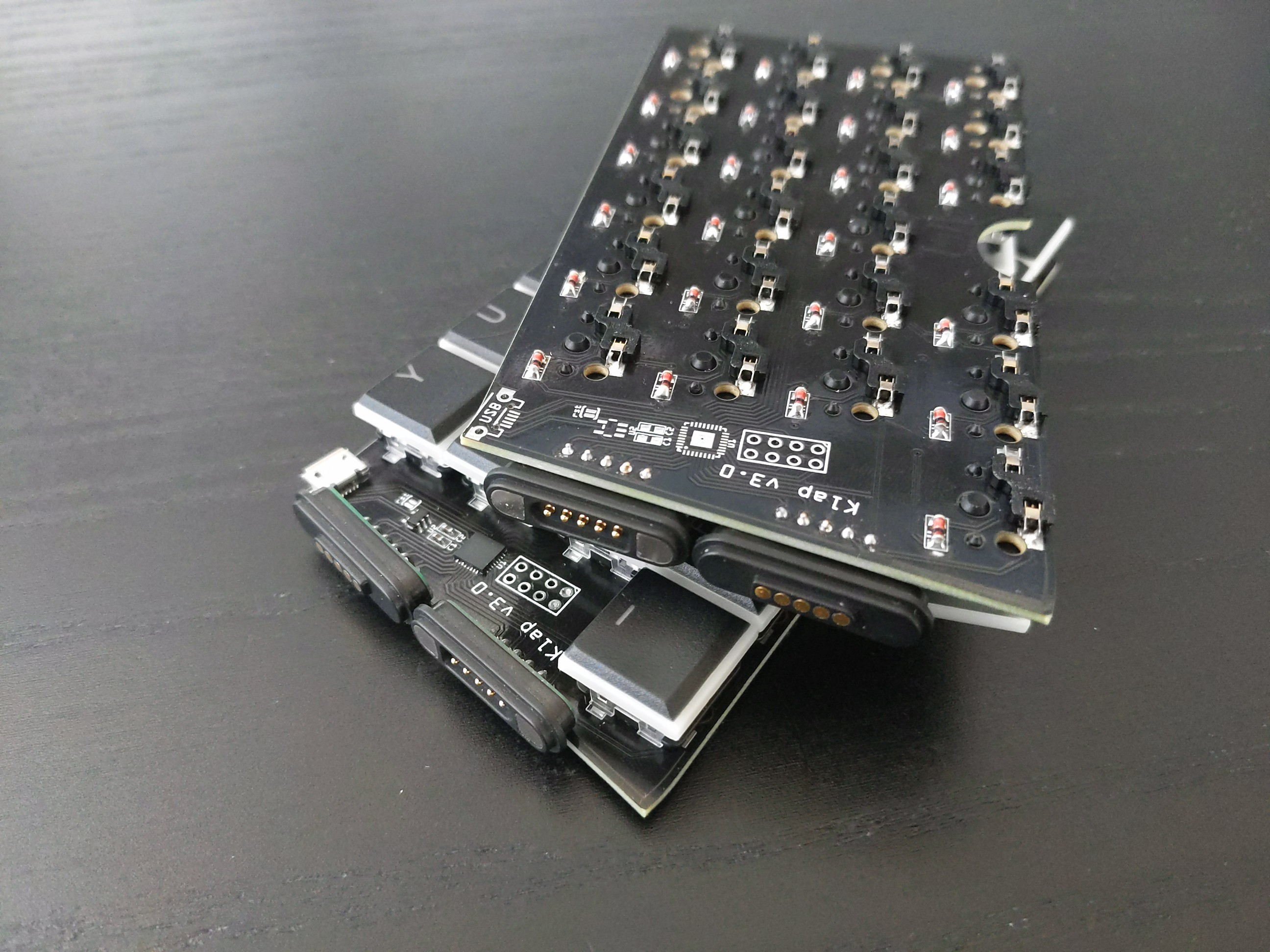
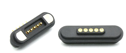
Hi, Were the juction force of pogo connectors enough to keep both halfs attached ? Would it be possible to use the keyboard placed on knees for example in car typing ?