 Johan
JohanThe Circuit and PCBs
The circuit I chose used a diode to make the 555's charge-discharge cycle strongly asymmetric, producing the narrow pulse wave needed to control a hobby servo. I added trim potentiometers that would let me configure the minimum and maximum duration of the control pulses, plus an envelope detector that would sense the servo control output from the 555 and light an indicator LED in response. I also included a three-way switch to select either the tester's own power supply or a separate supply as the source of the servo power output, or disable the power output.
I placed most of the circuitry on a 400-hole breadboard-style experiment board. The output ports, indicator LEDs (green for power input, red for servo power output and yellow for servo control output) and trim pots (min pulse length, max pulse length coarse/fine, pulse frequency and envelope detector sensitivity) were placed on three panel-mounted auxiliary boards.
The auxiliary boards and panel components (DC jacks, toggle switches, etc.) were connected to the main board via JST XH connectors. The eight XH receptables I ended up with required a lot of space on the main board, but I considered this flexible solution superior to soldered-in wires that would make the electronics difficult to install in the enclosure or remove for repair or modification.
The Enclosure and Control Panel
For the enclosure, I chose the Future Box FB16 as a starting point. The FB16 is a horizontal slab of black plastic, about 14×11×4 cm large, with rubber feet and removable lid and side walls. There are prepared attachment points for screws on the inside of the lid and bottom part, but I would have to drill and cut additional holes for PCB screws and panel components.
The 400-hole experiment board did not come with screw holes, so I'd have to drill those, too, or attach the main board in some other way. I chose to clamp each of its corners between two washers on a screw, since this preserved the greatest amount of board area and let me utilize some of the attachment points in the project box. Rectangular holes for trim pots were made with the Dremel "MultiPurpose Cutting Bit" (561), which worked acceptably once I knew what to watch out for (i.e. the bit drifting off and cutting all over the place).
Decals for the legends on the lid and side walls were printed on ordinary paper, laminated and then glued to the FB16 with contact adhesive. I cut holes for panel components in the printed decals before lamination, then cut corresponding holes in the laminate. Screw holes were drilled straight through the laminate.
Postmortem Commentary
- This project was a near-complete success. I got to practice several useful skills and managed to implement all the planned functionality in a reasonably neat package. My process (design the circuit, test it on a breadboard, design PCBs and enclosure, solder PCBs, test PCBs, fabricate enclosure, assemble and test complete device) worked as intended. I never felt like I was pushing my luck.
- The way the enclosure model is designed in FreeCAD makes updating it tedious and error-prone. Next time I'll use abstract construction geometry instead of derived model features to provide reference datums.
- The enclosure is not quite as neat as it could have been. Some of the drilled holes were off by a few millimeters. I had to drill additional holes for the LED PCB, then widen the holes a bit to get the screws in place. It took some experimentation to produce approximately rectangular holes with the Dremel cutting bit. The bit will quickly drift off and make a mess unless carefully handled. The attachment points in the FB16 box have 2 mm holes and cracked when I inserted my 2.8×13 mm sheet metal screws (the smallest I could find). Should I have drilled out the holes a little more first?
- The jumper wire connections are somewhat messy, especially on the main board. I should consider better ways to design, document and construct those....
 Andy Smith
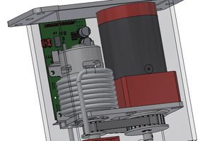
 patchartrand
 Bulbul
 Quinn
Quinn