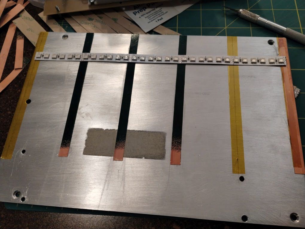
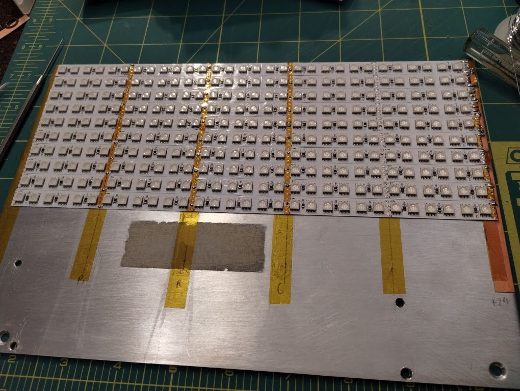
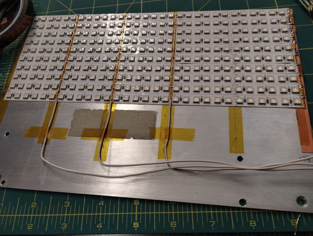
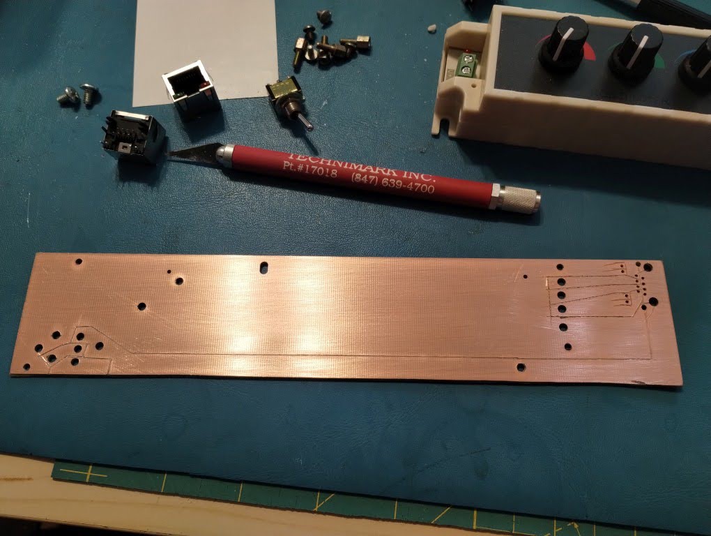
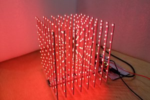
• LED Wiring

    Quinn03/22/2024 at 17:14 0 comments

    While LED strips are super convenient, the nuisance of them is in making the connections, especially if you have a bunch of segments.  The combination of wire sized for the current, the tightly spaced pads, and the flexible PCB makes it fiddly, and prone to break.  My initial intentions was to make a kinda bus bar PCB at one end.  When I got to implementing that I decided I didn't want to spend that much time cutting so many narrow traces.

    Plan 2

    My second plan stuck with the bus bar idea, but just used 4 separate ones, placed at 4 different solder points on the strip.  There is no reason that the strips need to be powered from the end, or even all at the same point.

    So I glued 4 strips of thin single sided copper clad board to the aluminum plate, 3 of which with solder resist that I would remove where I wanted to connect.

    The other connection points I put a strip of tape so the pads on the bottom wouldn't short.

    I was worried this would be too hard to solderr, through the flex, onto the plane of the copper, which was bonded to the aluminum plate.  It was.

    It certainly could have been done with a bunch of area heat, etc, but decided it wasn't worth it and went with plan 3.

    Plan 3 (final)

    I realized it would be easier to simply use tape to cover the unneeded connections and solder a wire across the strips.  This proved to be quite easy, and I'd recommend it for others making arrays out of LED strips.

    Again, tape isolated the bottom contacts from the aluminum.

    On the end, I opted to leave a copper strip for the common connection for current capacity.

    Prepping the strips:

    Bus wires

    I'm happy with the end construction.  It's clean, was pretty easy, and is quite robust.

  • Main Board Finished

    Quinn03/22/2024 at 16:59 0 comments

    As noted, I cut this out by hand.

    Component holes

    I started by using ruler and scribe to add lines for the hole placements on the RJ45.  These connectors don't fit into common strip board, which is part of the reason for making my own board.  A metal created a nice pilot to drill.

    I repeated this for the DC Jack, switch and placement for second RJ45

    Traces

    Next I drew out the circuit on the backside and use an exato and ruler to isolate the traces..

    Mounting 

    Mounting holes were drilled and tapped.  I took care to make sure the stand off holes did not connect to any traces but ground.  While grounding the plate isn't required, the stand offs did handily end up doing so.

    I also drilled a couple holes for wires to solder to for connection to the dimmer.

    Result

    I kinda love how manual and h

  • Circuit Boards

    Quinn02/12/2024 at 21:52 0 comments

    To connect things, I hand made a couple circuit boards. This would make for a simple and clean assembly, minimizing wires, while also serving as mounting.

    I do schematics and layout as part of my paid just, so usually try to do things differently for hobby projects.  In this case, I designed and cut it by hand, without schematic

    I used some copper clad fiberglass board, and hand cut the needed traces.  Holes were all drilled.

    For the main board, I used 0.063" single sided to provide some rigidity.  I only needed a single side, and not having the second meant I didn't need to create isolation.

    For the second board, I planned on using dual sided 0.032, and single sided 0.010".  After cutting traces and drilling, these would be glued together into a mixed stackup 3 layer board.  While that sounds complex, the need for 4 parallel wired connections made the simpler then a more complicated layout to cut.  The extra layer can be thought of as simply a wire added on.

    It would be cleaner to have these boards made (costing a bunch more for shipping), or etch one, but the time to create components in a library, do schematics, route, and then make it would have been longer.  

    This process took less than 2hr, requiring only a hobby knife, ruler, scribe(or pencil), punch and drill. As it was so basic I never drew schematics or anything.

  • Components

    Quinn02/12/2024 at 21:21 0 comments

    I started by collecting the parts I would need.

    Mechanics

    I decided on an aluminum plate from my stock.  This came off a card module that was obsolete and long torn down.  The aluminum was a good size already so I wouldn't need to cut it.  There was printing on one side, but some work with 120grit sand paper cleaned it off, and refreshed the brushed finish.  The aluminum would also help as a heat sink.

    I also dug out some small stand offs from stock.  I have so many of this short ones with 4-40 threads that come from panel mounted D-sub connectors.

    Instead of nuts, I opted to just tap holes into the PCB.  It makes for quicker construction.  Of course it isn't a very strong material to hold threads, but none of it would take a lot of strain.  In addition to the 4-40, I also used two 6-32 screws to mount the dimmer.

    LEDs

    For bulk LEDs, you can't beat generic LED strips.  I got 5m of 120 led/m strip for 11usd on aliexpress.  I opted for 24v variety as it means reduced current (doesn't need as thick of wires, and the higher voltage means less of the power is wasted in the series Rs.

    I only need 2.5m for this project, and will save the other half in case I like this panel enough to make another one.

    The strip was unsoldered into it's 0.5m lengths, and those were cut in half again to nicely fit across the panel.

    Dimmer

    I wanted something that was simple, and remembering settings.  There are all sorts of programmable ones, which fade, have an IR remote, etc, but I just wanted basic.

    I ended up getting one with three knobs, one for each color.  Supports 12-24v, 3a max/channel, which is a good match for the strip.

    I opted to add a simple power switch as well.

    Power

    I already have a 24v 4.5a DC power supply I often have at these events, so it was a logical fit. If I ever need both this flood and the amp I usually use it with at the same time, I'll get another one.

    Connections

    The supply has a common 2.5mm barrel plug, so I pulled a circuit board mount socket from stock.

    I wanted to be able to extend the panel so that the same supply and dimmer could be used for multiple.  I find RJ45 jacks and cables to be cheap and accessible multi pin connections, so went with that here as well.  A simple ethernet cable can be used to connect them.  The 8 pins would allow 4 for power, 3 for the R, G and B returns, and one for ground in case I wanted to power any circuitry on the second panel.

    To connect everything together I decided to go with a circuit board.  As it was a one-off and very simple, it was quicker to hand make it rather than having a PCB made or for me to etch it.

    The circuit board serves as a mounting, but also tidy connections without having an unreliable mess of wires.