 Bulbul
Getting straight to the core to try to explain it simply, the anwaar amulet is a 2 piece design.
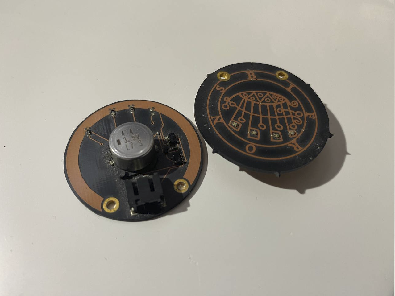
The bottom board (I refer to them as the base board) can be thought of as a hyper specific development board. In this case I ended up using an attiny 1616. On top of that it also includes an energy source (15F Hybrid Capacitor) as well as all the power management for charging and providing a stable VDD rail.
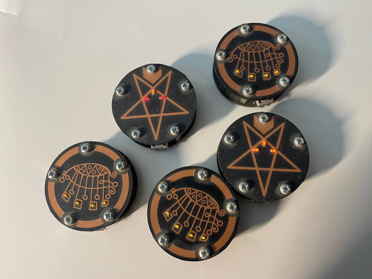
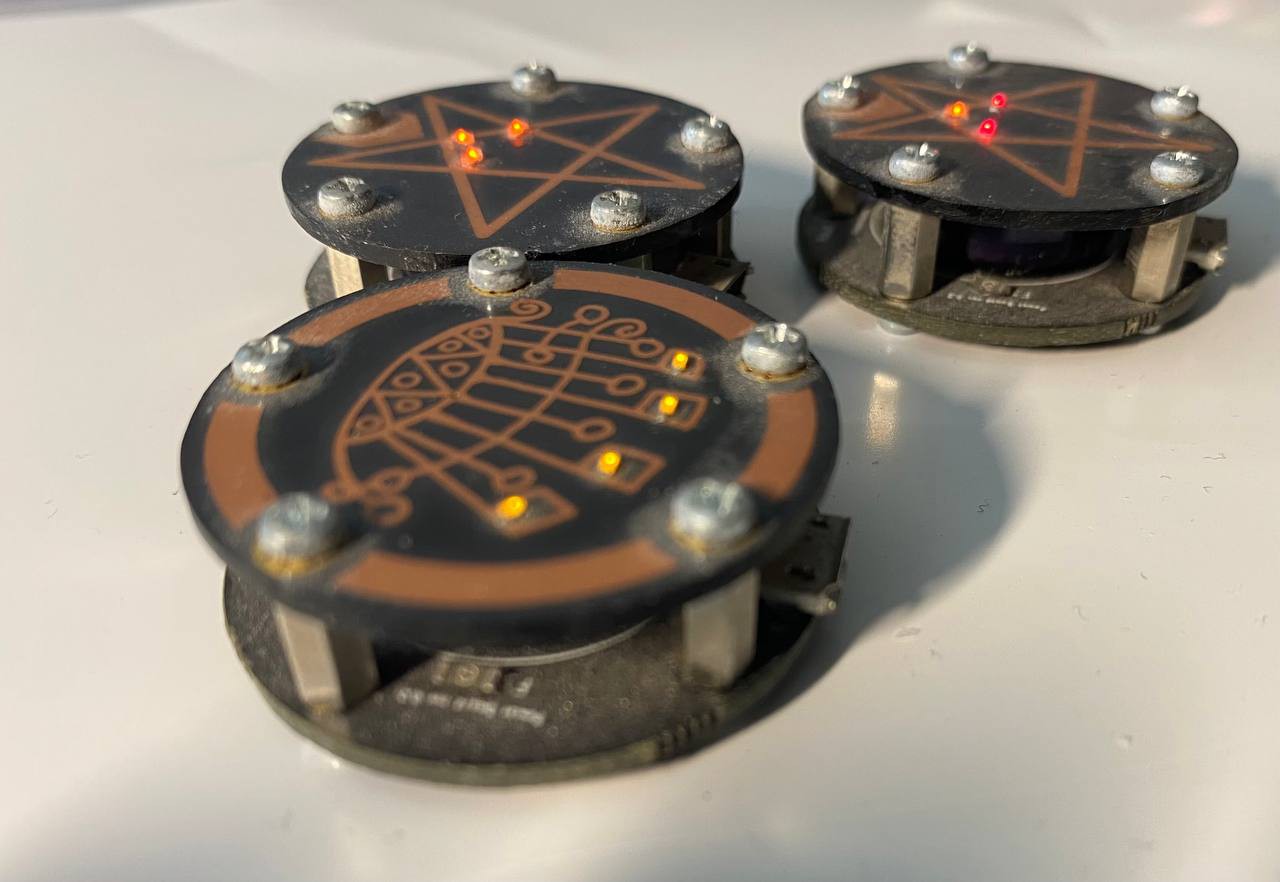
The top board (which i refer to as the face plate) connects to the base board using a 10 pin header/socket and secures with five m.2 screws/standoffs. The face plate is intended to carry artistic designs and circuits, the obvious use being a fun blinkies. Taking it a step further I like to find ways I can integrate the copper of the circuit into the artistic design itself!


 The first amulet!
 fool
fool
 Gee Bartlett
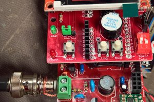
 Jon Kunkee
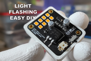
 DIY GUY Chris