 Andy
AndyI will update the project soon, stay tuned.
Let's talk about reduction gear
Reduction gear is the main part of an industrial robot arm. As a hobby project, nobody wants the parts too expensive , 3d printed reduction gearbox is definitely a good way to do that. Other robot arm projects are using timing belts and pulleys that is hard to achieve high reduction ratios in small space. Normal used gearbox is also hard to get high ratio and hard to assembly. So I decided to use something else.
Planetary gear
Planetary gear(https://en.wikipedia.org/wiki/Epicyclic_gearing) is a good way to get high ratio reduction in small space. I've tried to design one of these. But if I want to get higher ratio, say more than 20:1, that's hard using one stage system in small space. And to reduce friction, we must add lots of small bearings. That's not what I want.
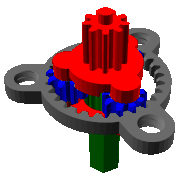 Animation of a planetary gear.
Harmonic Drive
Harmonic Drive(https://en.wikipedia.org/wiki/Harmonic_drive) is another kind of reduction gear system, this is a good solution for robotics, because harmonic drive can achieve high ratio in small space. Lots of industrial robot arm are using harmonic drive as those reduction gear. So I decided to use harmonic drive in my design.

In harmonic drive system, the most difficult part is the flex spline part. Because the flex spline gear need to be flexible, so that's really hard to manufacture. Leading harmonic drive is very expensive. That's not suitable for hobby projects. Another drawback is harmonic drive in the market is very large in footprint, not really good for small system like our robot arm.
So we can't buy one, how about we design one and print it. That's what I've thinking. The result turned out working great. In the next section , I will talk about how I designed and printed the harmonic drive.
Design and Print Harmonic Drive
That's not very hard to design a harmonic drive. Just like normal gear design using any CAD tools( like solidworks, autodesk fusion 360, sketchup, etc).
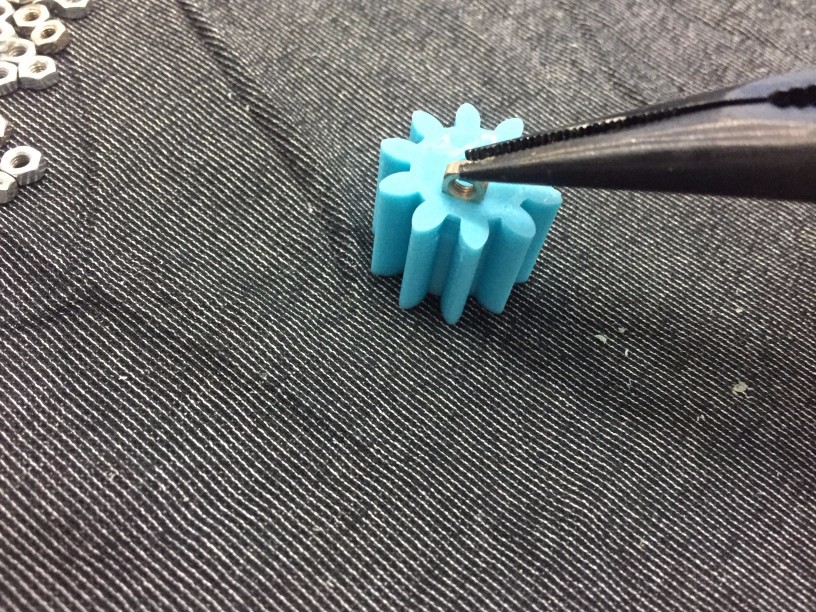
First, pick up the gear's teeth numbers. I want build a 1:50 ratio (for ARM1), so I set the outer(circular spline) teeth to 102, so the flex spline should be 100 teeth. The ratio is (102-100)/100 = 1:50.
The module I selected 0.8 for easy to print and not very large in diameter.
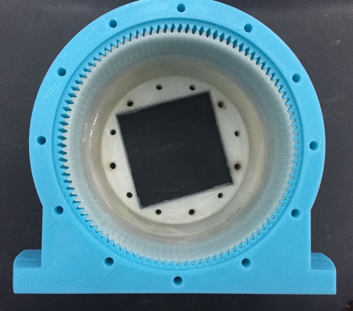
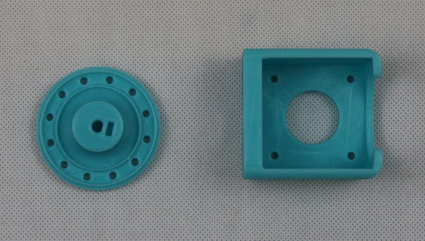
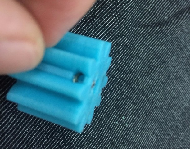
I printed out, but turned out it's not very usable, because that's not very smooth. You can see the picture, the flex spline and circular spline are too tight. The motor is hardly to move.
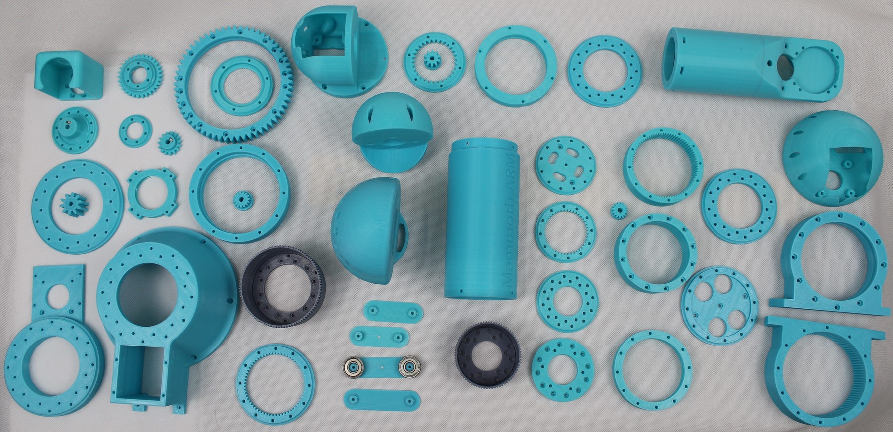
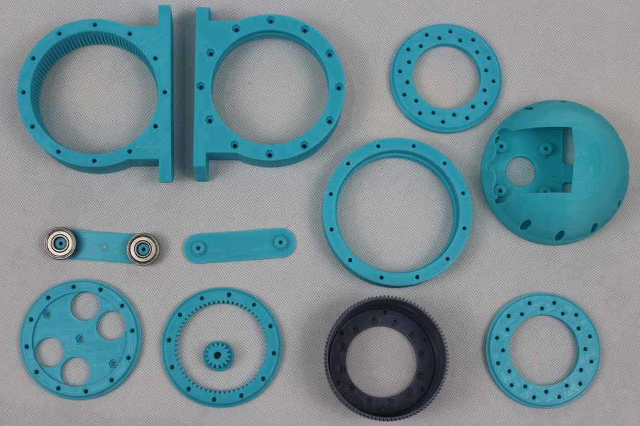
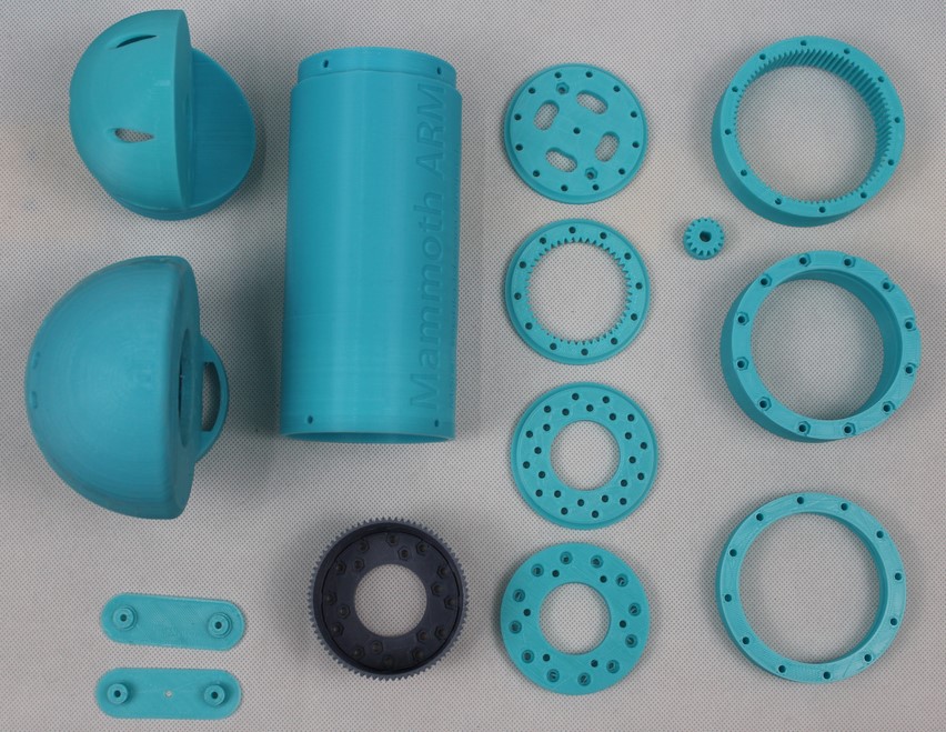
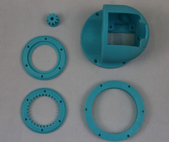
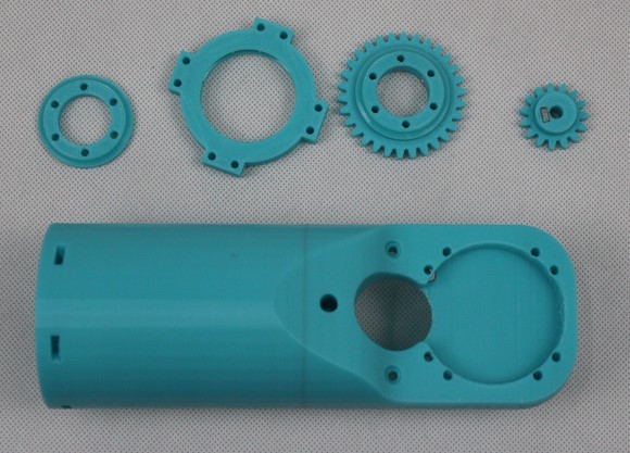
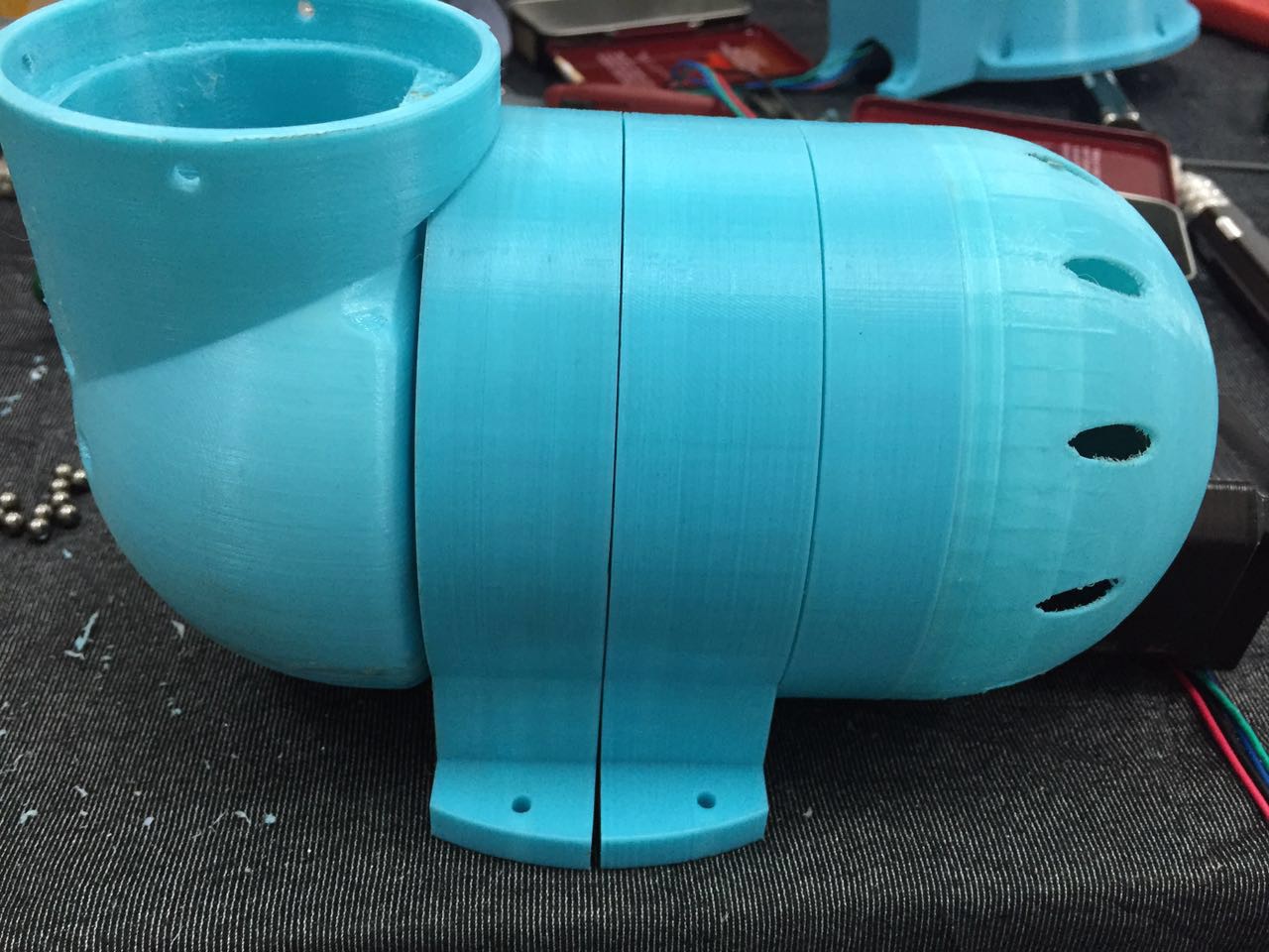
![]() Here is all the printed parts
Here is all the printed parts
 Here is all the printed parts
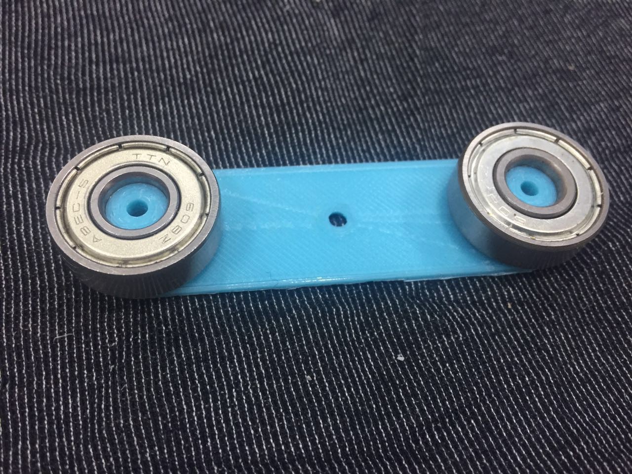
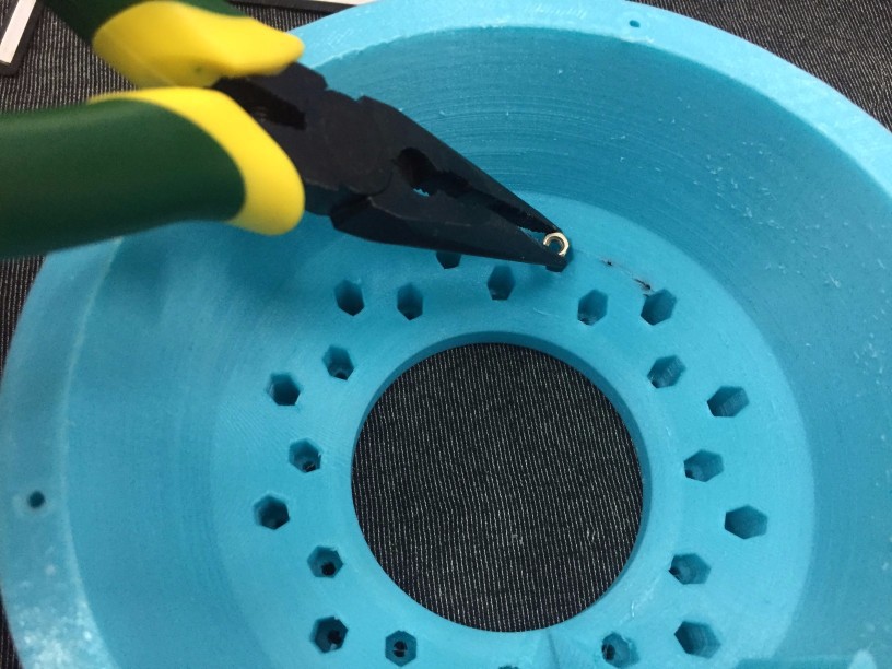
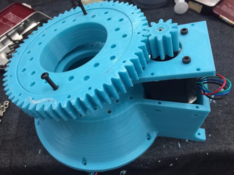
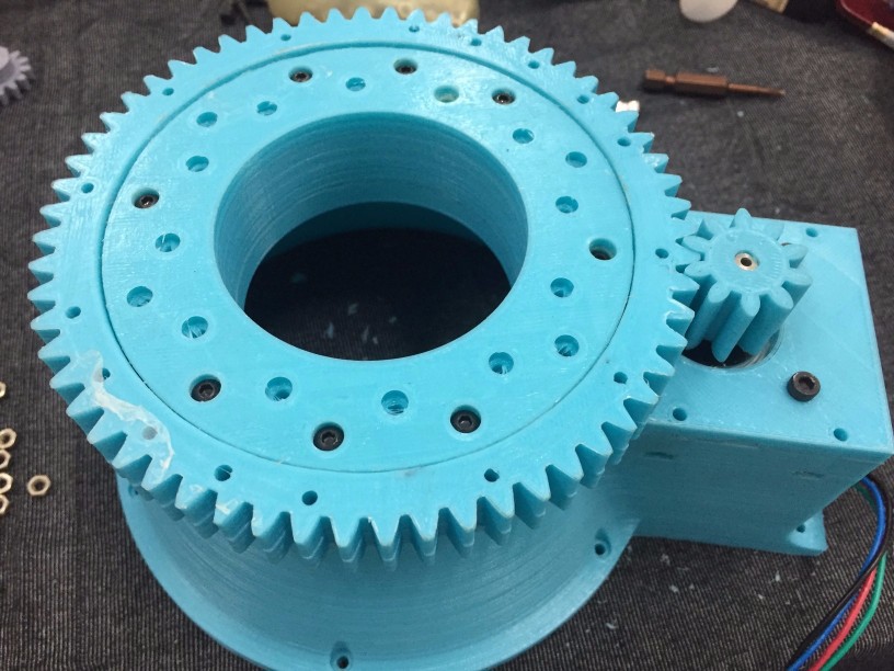
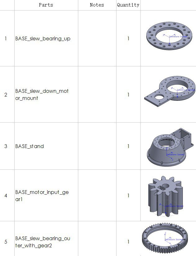
Base parts:
ARM1 parts:
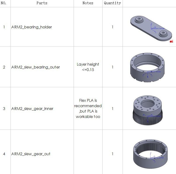
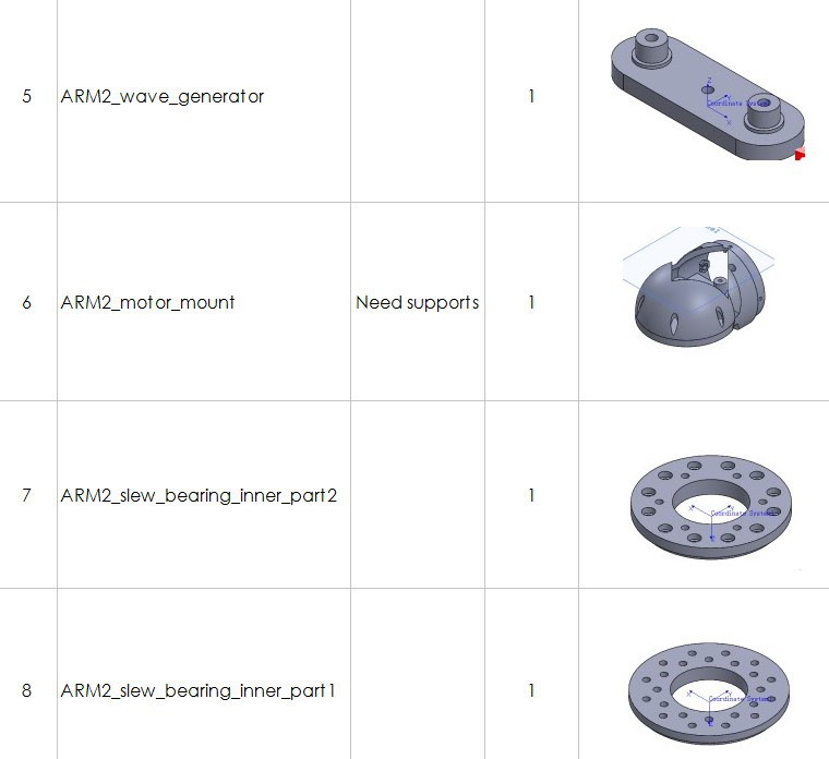
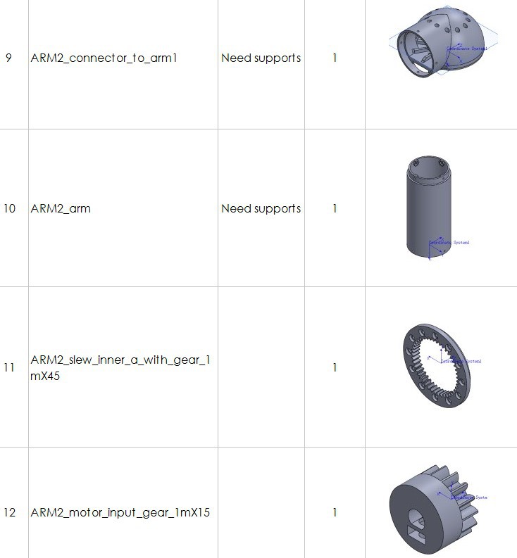
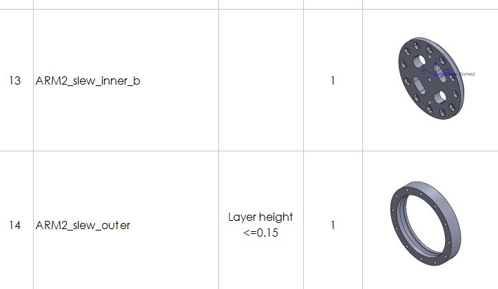
ARM2 parts:
ARM3 parts:
ARM4 parts:
ARM56 parts:
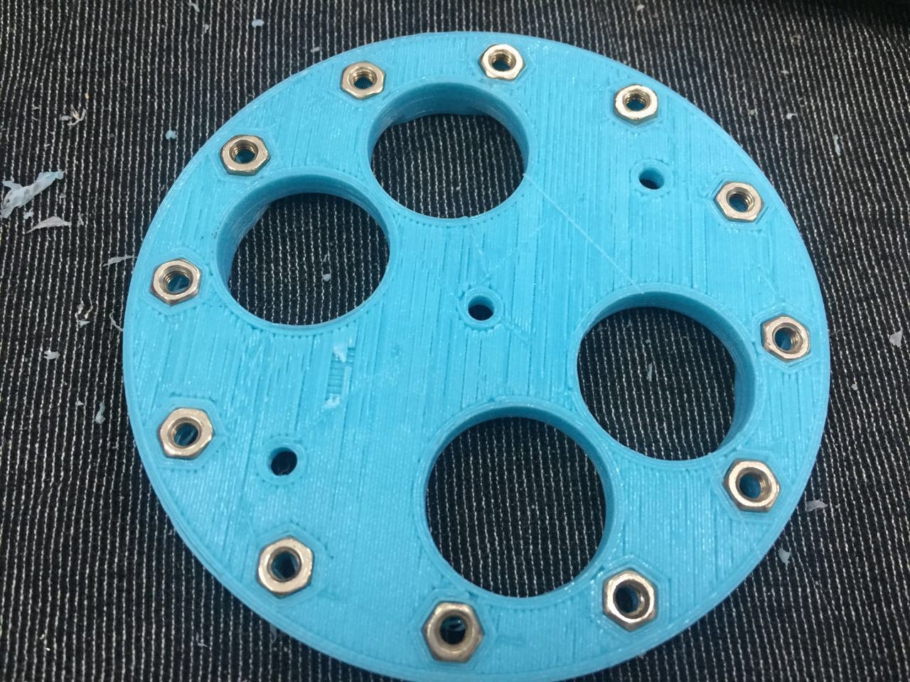
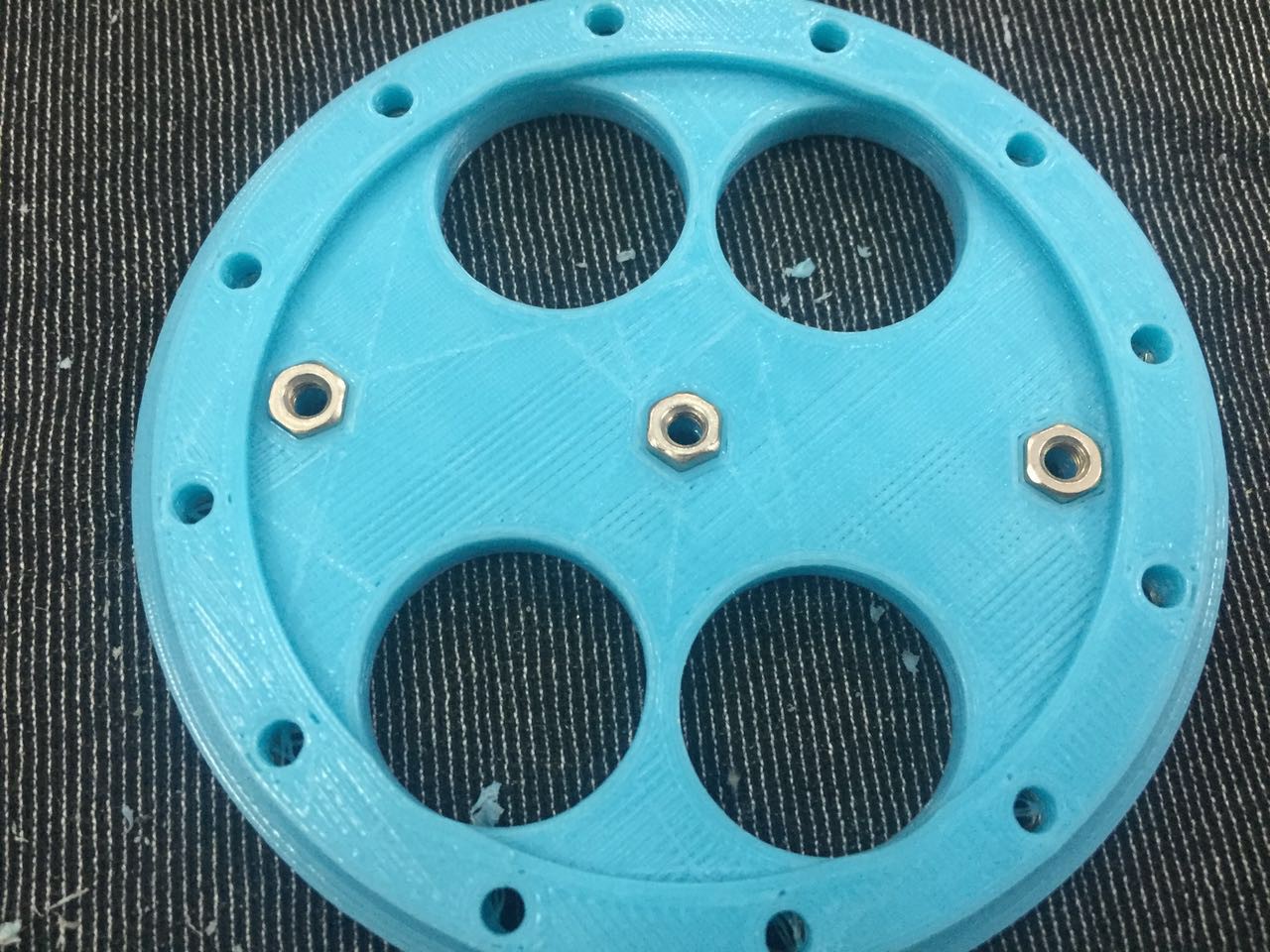

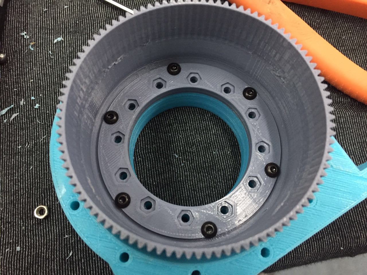
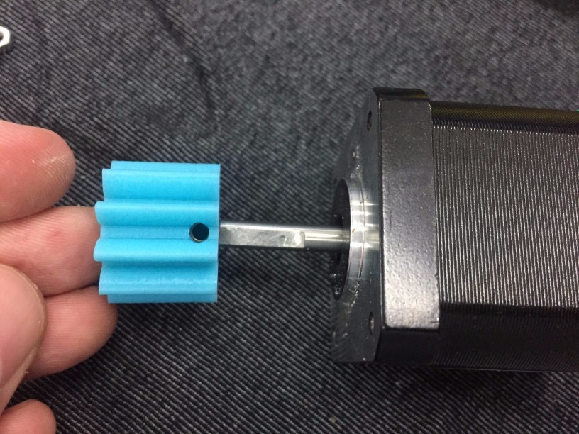
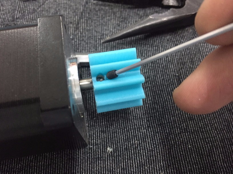
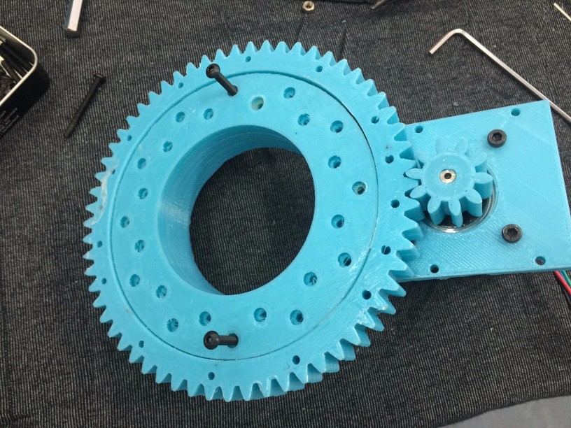
 Put ARM1_slew_inner_a_with_gear_1mX60
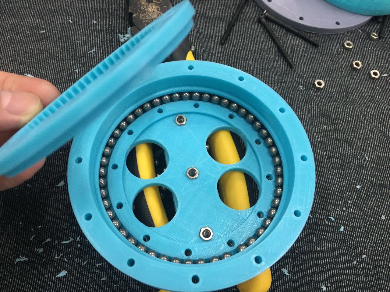 put ARM1_input_gear_1mX15
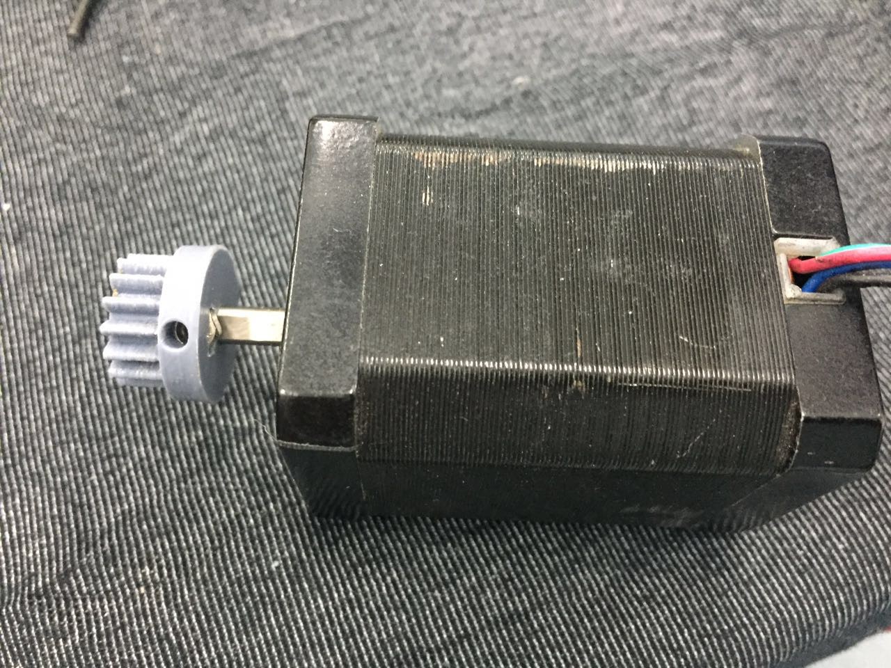 4 M3X14 to fix the motor.
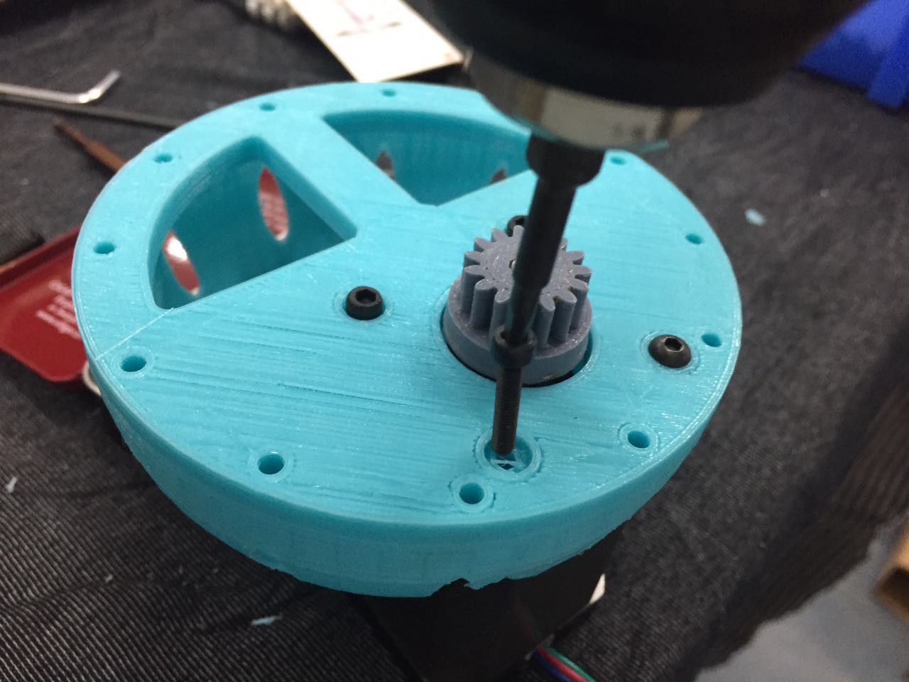
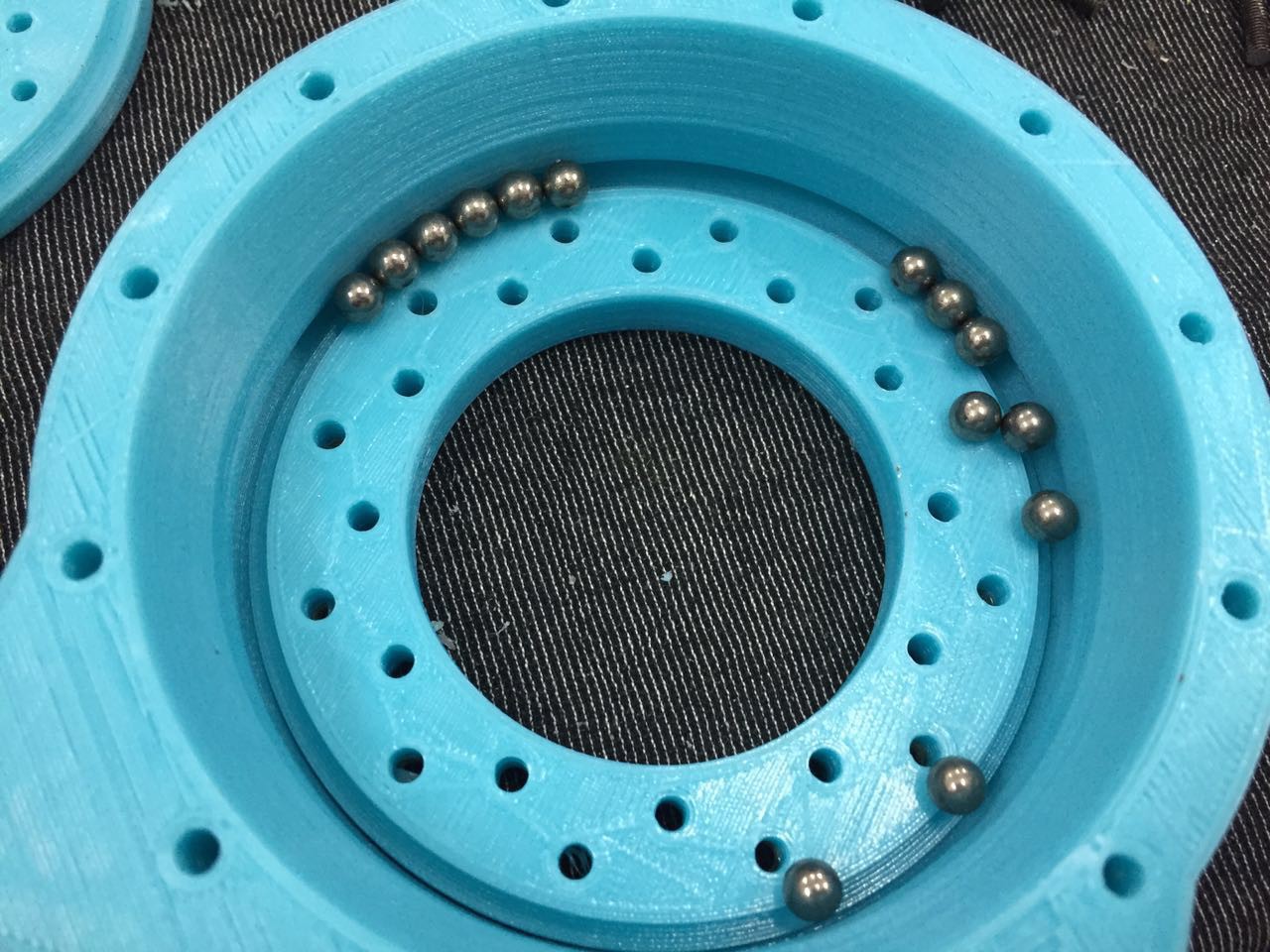

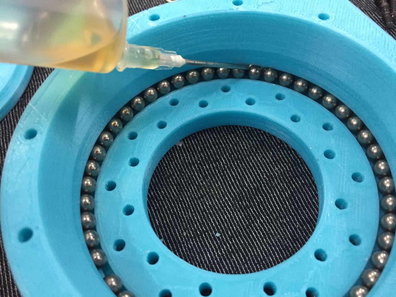
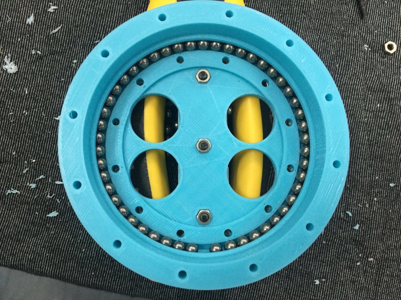
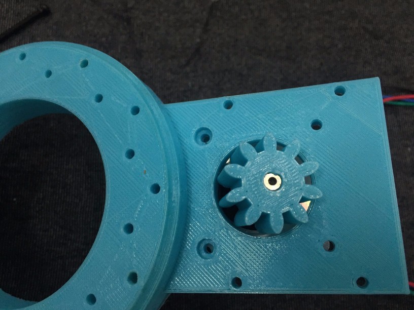
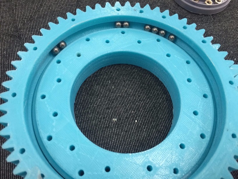
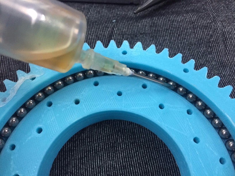
 Put those together. Don't forget nuts on ARM1_slew_bearing_outer
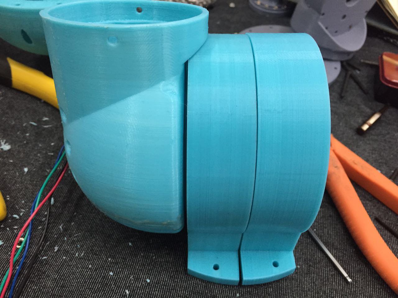 Put all the parts together, done.
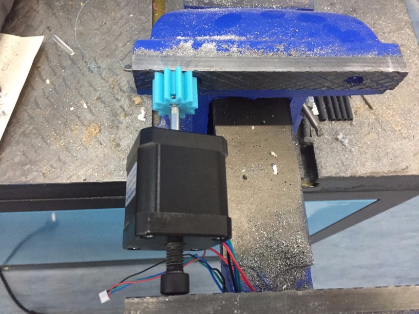

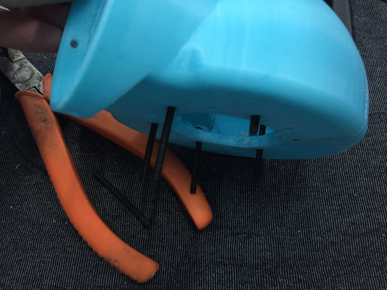
 Put those parts together.
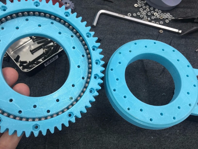

 Val
Val
 Enrico
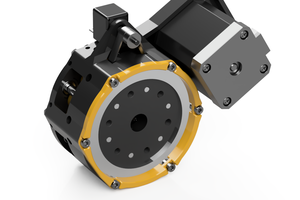
 Damian Lickindorf
What's the status of this project? Why hasn't the world flocked to this??? :-)