 Ian Dunn
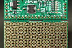
I designed this controller board to work with my Mighty Mule swing gate actuator, but it will work with pretty much any 12V swing gate actuator. If you’ve got an old Mighty Mule controller box like mine, the board will even fit into the same mounting holes as the original Mighty Mule controller. It’s pretty simple to operate once it’s built. It opens the gate, stops when the open limit is reached. Next the gate closes and stops when the close limit switch is reached. It also has an extra relay for a magnetic latch. It can be remotely controlled with a cheap 433Mhz relay from eBay. And the best part is that you can easily change the code to make your gate do anything you want! It’s based on everybody’s new favorite $4 micro controller, the Raspberry Pi Pico. I used some SRD-12VDC single pole relays to form an “H bridge” with relays. On my first attempt of this circuit I used some TIP-120 Darlington transistors to switch the motor, but I quickly found out that a stalled gate causes enough fault current to burn out a TIP-120 faster than the fuse can blow. The relays are big and clunky but they can handle a lot more abuse. This board requires limit switches. It can be used with the limit switches built into your gate actuator if it has them, external limit switches, or hall effect sensors. If you want to use the limit switches built into your actuator, I recommend taking the case off of the actuator so you can see what wire goes to what limit switch. I learned the hard way that you can smash the internal limit switches to bits if you don’t stop the motor when the limit switches are at their limit! For this reason, it’s important to verify that you’ve got the motor hooked up in the correct polarity when you first turn it on. There’s a status LED on the board for open and for close, so just make sure that the correct LED is lit when the gate is in motion one way or the other. If it’s backwards, reverse the motor leads. If you’re looking for some external limit switches, I recommend searching for ME-8104 limit switches. They are cheap, robust and weatherproof. You could also use a Hall effect sensor. I added a +5VDC terminal to power a Hall effect switch. It’s simply connected to the L7805 voltage regulator. One thing the board does not include is a charge controller. I didn’t bother to try to add this on, because small solar charge controllers are really cheap easy to find and I think they probably do a better job. You will also need a sizable lead acid battery. The terminals on the board are relatively self explanatory. Connect the actuator motor, the limit switches, power and a power switch. The external power switch is supposed to connect to the 1/0 terminals. If you don’t want to use an external power switch, just put a jumper across the 1/0 terminals. The NC and NO terminals are for a latch or a mag lock, however you could change the code to make this relay do something else like a light or something. I’ve included the Gerber file if you want to order the board exactly as it is. If you want to make changes to the design, I’ve added the .JSON files for the schematic and the PCB that can be imported into Easy EDA. The Bill of materials includes everything on the PCB. And of course the Arduino sketch is also in the files. I hope this saves someone else from going through the trouble of re engineering a Mighty Mule gate opener control board!
0%
0%
Replacement Mighty Mule swing gate control board
Replace your Mighty Mule swing gate controller with an open source controller.
Become a Hackaday.io member
Already have an account? Log in.
Just one more thing
To make the experience fit your profile, pick a username and tell us what interests you.
Pick an awesome username
hackaday.io/
Your profile's URL: hackaday.io/username. Max 25 alphanumeric characters.
Pick a few interests
Projects that share your interests
People that share your interests


 fruchti
 elmameto
 J3TTBlack88
 Timo Birnschein
I am trying to solve this exact problem, my parents have an MM271 and the circuit board needs to be replaced, but they don't sell the board for that model.