 flynnwt
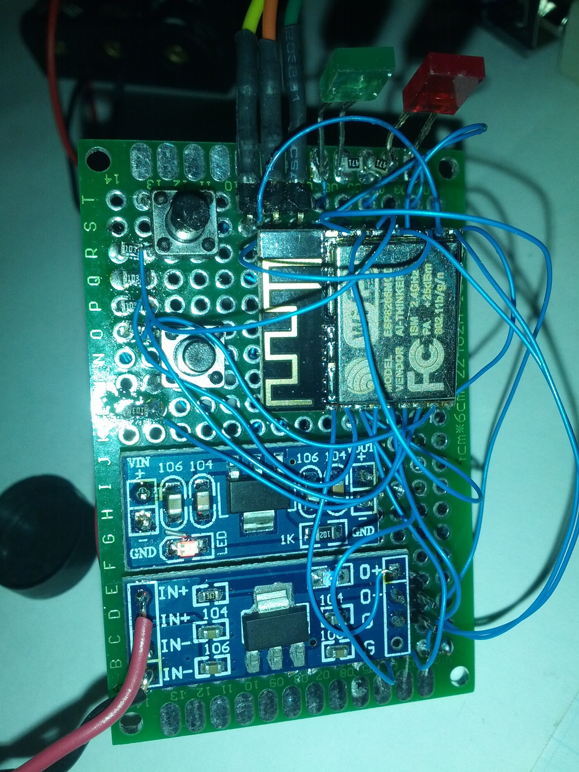
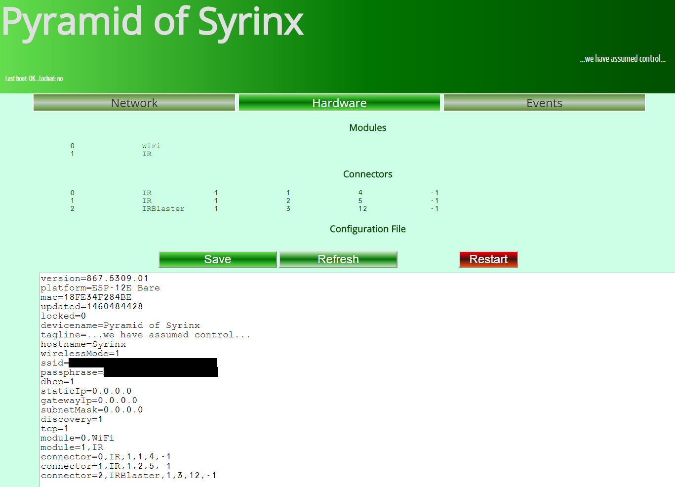
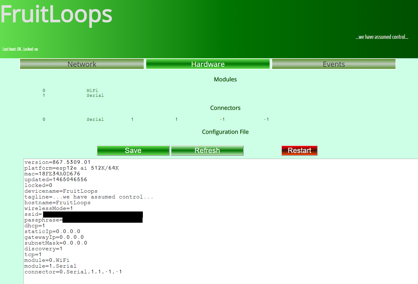
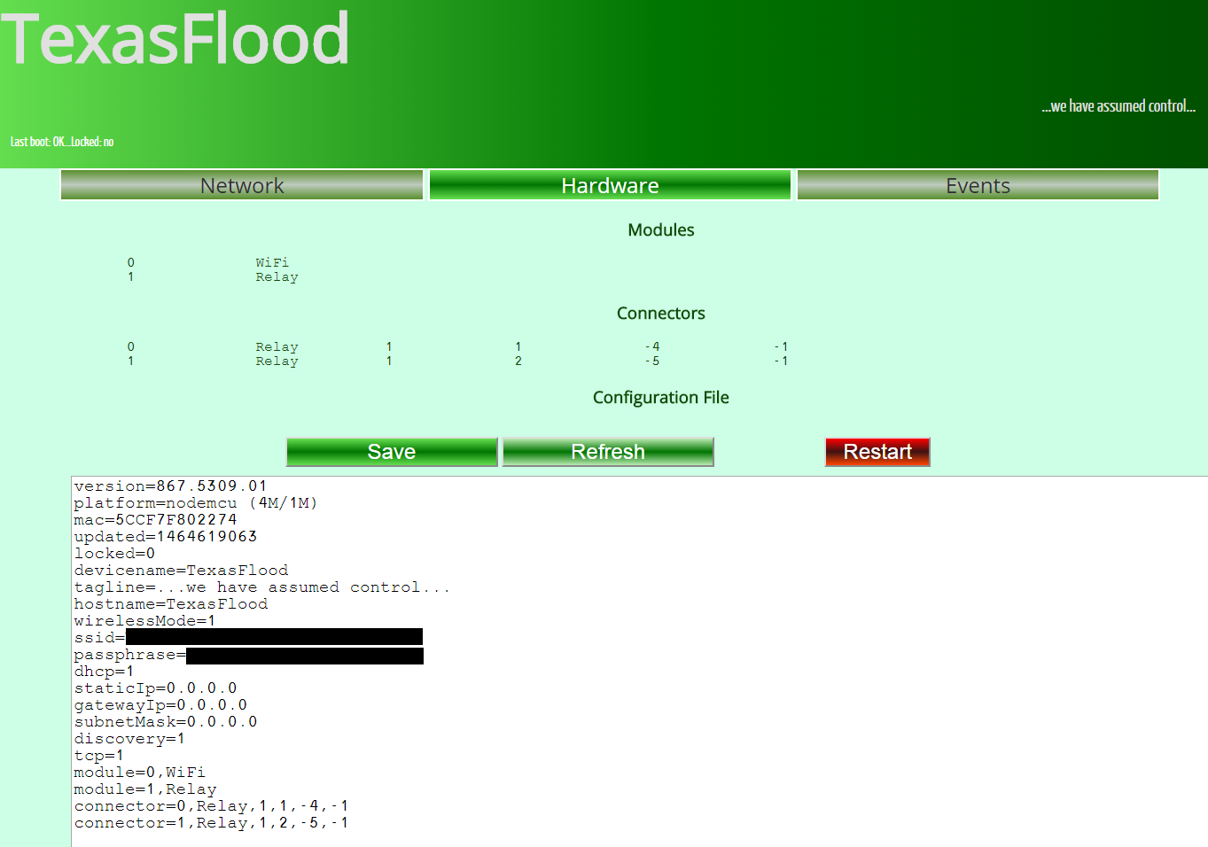
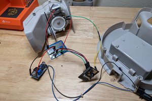
This is an introductory project to the ESP8266. Adding some small bits of hardware and programming creates a wireless bridge to infrared-controlled devices. I wanted to emulate the Global Cache protocol since I have an ITach Wifi2IR and other software (Homeseer) that understands its protocol. Some simple GPIO hardware and coding allows discovery and device control over udp/tcp/http for infrared, closure sensing, and relays.
The ESP8266 also has plenty of power to add new capabilities like distributed control, sensing, communication and scheduling for many kinds of mancave automation.


 Bradley Austin Davis
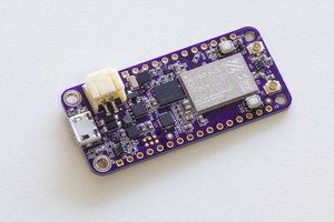
 Jared
Jared
 anlumo
 Fingoti
Thanks for that. I'll have a tinker around with it and let you know how I go.