 Casual Cyborg
I've searched for a wearable Internet of Things development platform for my
needs, and I didn't find what I wanted. Sure, there's a bunch of IoT
wearable development boards out there. Some were all in one designs
with gyroscopes and accelerometers for watches... but no analog
ports. Some were Bluetooth, but not Wifi capable, and without that,
WiFi mesh capable. One is sewable. I don't want to sew, and I had a
lot of signal problems in sewable circuits. None had all in one cable
connects, and I don't want to solder new wires directly to the
board. And most of them don't use the Arduino eco-system, which in my
opinion, is the most user friendly, community supported, hardware
peripheral rich eco-system on the planet.
So, I made one.
Here's a list of features that first version of the the board comes with.
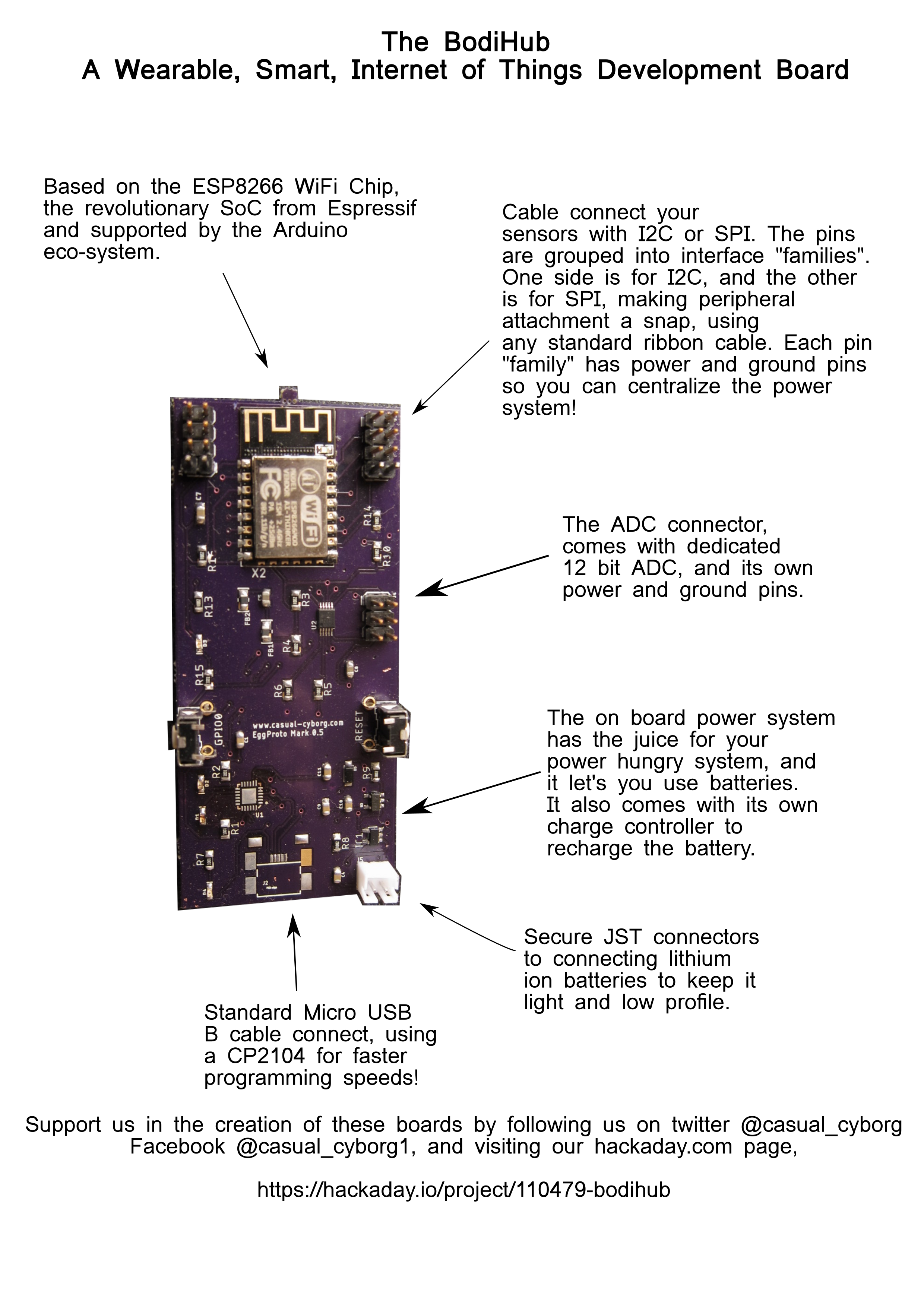
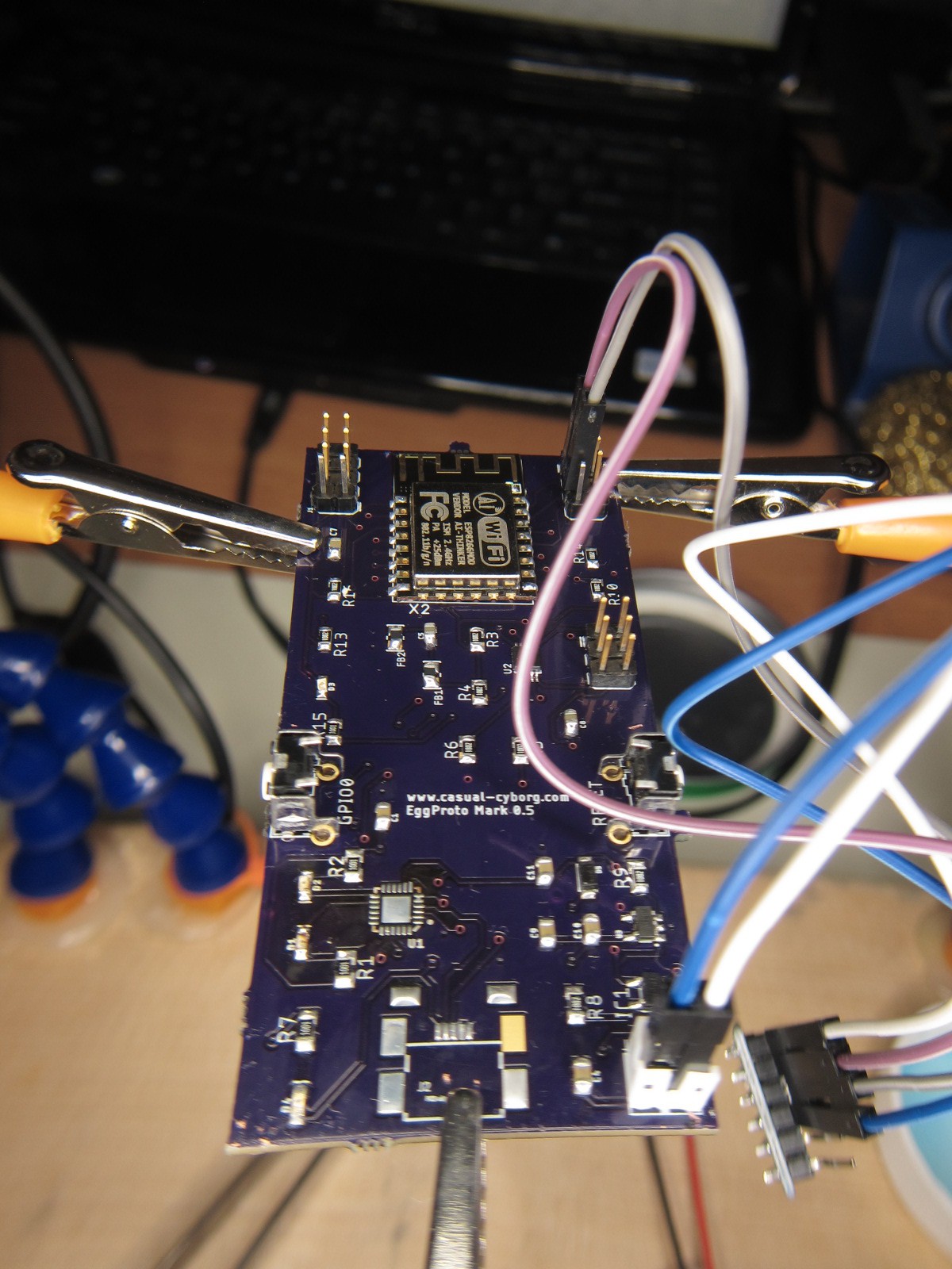
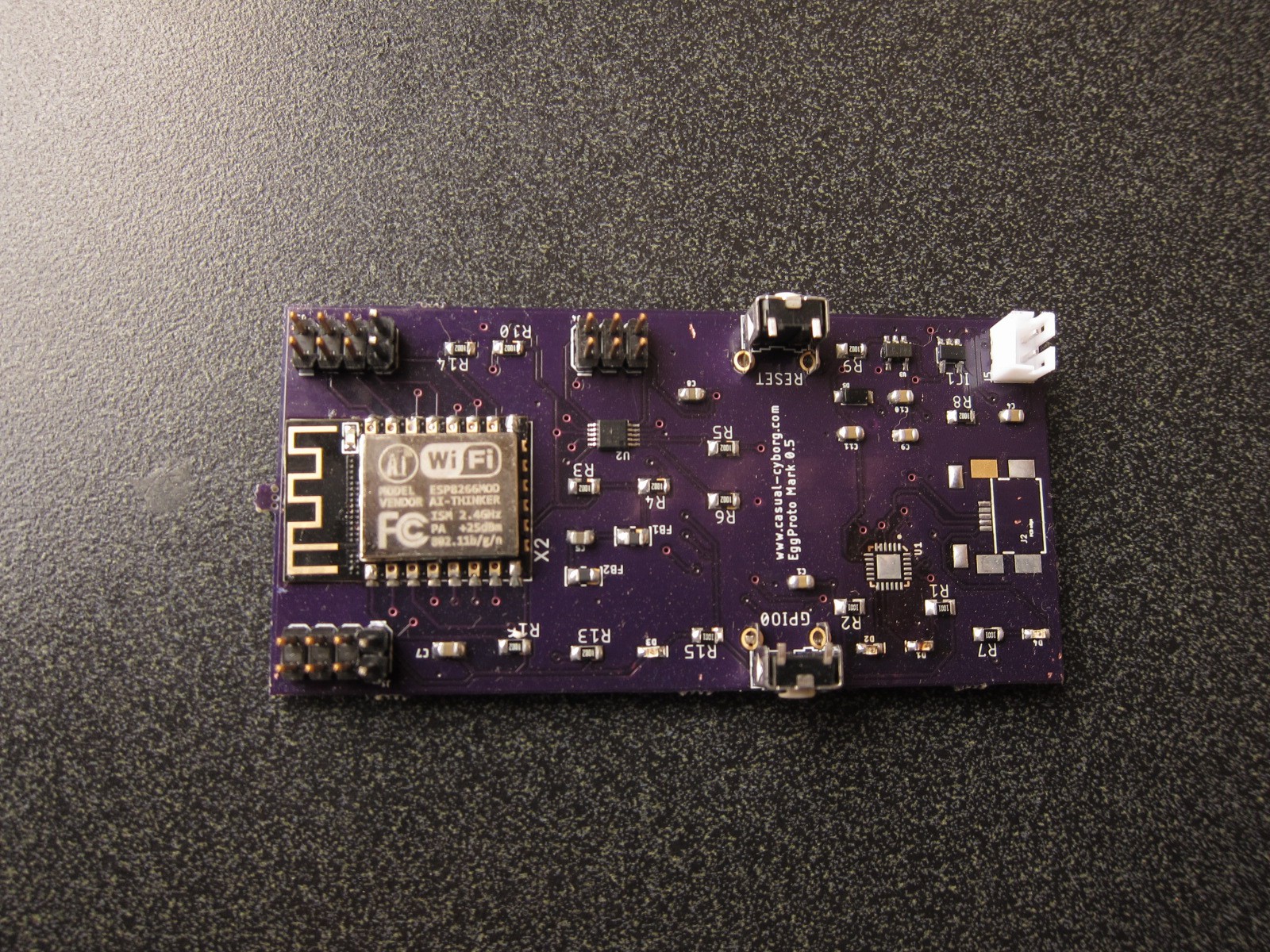
- The board is based on the ESP8266 SoC (System on a Chip) WiFi chip, which is 802.11 b/g/n compliant. The ESP8266 turned the world on its head when it first came out, since it was a programmable WiFi micro-controller all in one chip for a low price. We're currently using the ESP-12F, which has 36 kilobytes of SRAM, and 4MB of external flash ram for user program storage. It's a 32 bit microcontroller with an average speed of 80MHz, and can clock up to 160MHz. The greatest feature of the chip is it's compatible with the user-friendly Arduino development eco-system. This gives you access to a vast, worldwide community, an enormous software development library, and innumerable hardware peripherals, which makes this hard to beat.
- Cable connects! There are dedicated connectors, with pins dedicated to I2C or SPI. The connector groupings come with their own power and ground pins, so you can centralize your power system to the board. To use this feature, just include the standard Arduino "Wire" library, which comes standard with the Arduino IDE and PlatformIO. The pins use eight pin ribbon cables, which you can easily find at your favorite electronics vendor.
- Tired of the single, crappy 10 bit resolution ADC that the ESP8266 has? There's a dedicated ADC chip on board, which increases your ADC channels to four, and they're 12 bit in resolution! The pins also include their own power and ground pins as well. This gives you access to a vast array of analog sensors.
- The on board power system regulates and charges your battery via USB. You can use any svelte, light, lithium ion battery you want. Save weight and size while increasing your juice! The 2 pin JST connector makes it easy to attach.
- The board is a third the size of a credit card! That makes it small, light, and easy to attach to clothing. Or anything else you're using that needs a small form factor and space.
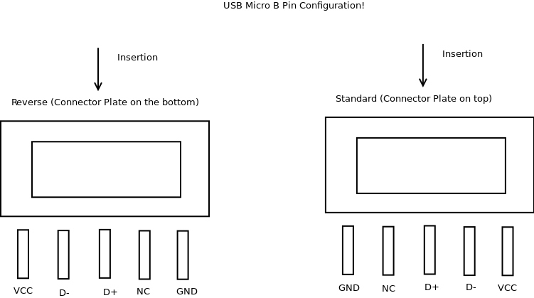
- It attaches to your USB power supply or computer using a standard USB Micro B connector, you know, the kind that comes with your Android phone. And the on board USB to UART controller does the talking to the ESP chip.
- It has a big power supply! Worried that you might be squeezing just a little too much juice with your program? Don't worry! With the on board regulator, you'll have more than enough current to take care of your power hungry needs.
What can you do with these capabilities? Here's a small list of projects being built with this development board.
- Boxing gloves that talk to each other while you smash the bag or someone else's face, and tell you how much force you used.
- Synchronized LED flow tools for fire and flow performers.
- A mesh network logistics tracking system that uses augmented reality interfaces to see what the boards see and what they're talking about. You can see a demonstration of the concept that I did at TechCrunch Disrupt NYC hackathon in 2016.
This is the first round, where the wifi cut out because it was clogged.
https://techcrunch.com/video/crate-zero/...
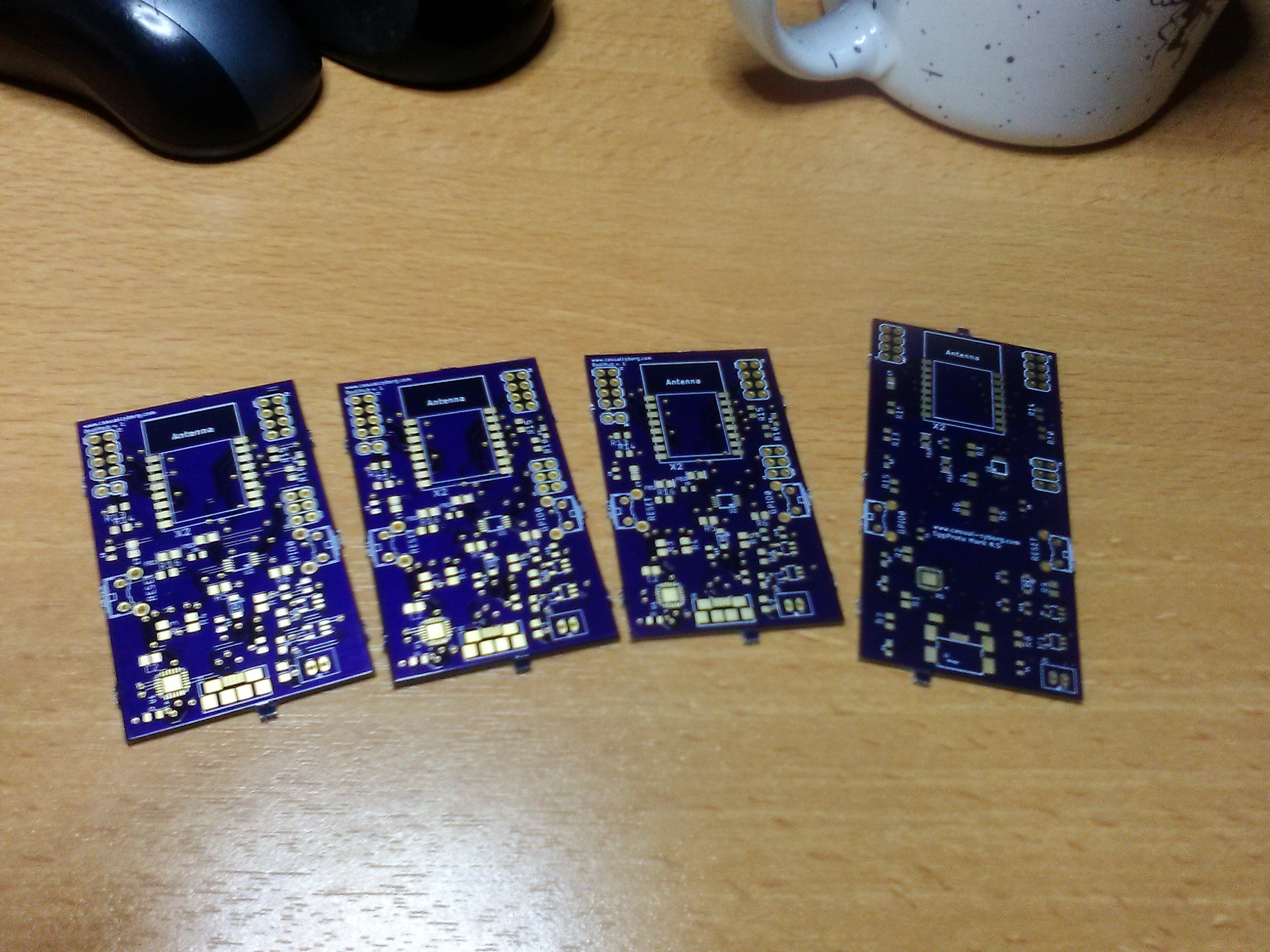

 We're going to send out the revised board tomorrow to fab with
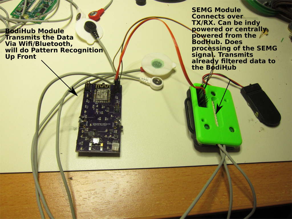


 Dave
Dave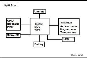
 Chaz
Chaz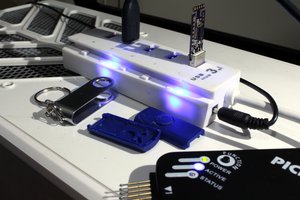
 Jarrett
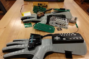
 Nolan Moore
It wasn't until I soldered on the 3.3V regulator which has a minimum of 600mA that the board started working properly. What kind of regulator are you using ?