 PUTMotorsport
SUPPLIES:
The LED’s we choose are REFOND RF-RURA30TS-CE, because of high viewing angle (120°), low profile (it was important for us to keep the PCB as low and light as possible), and high luminosity (542...1192mcd), the parameters of used diodes are shown below on attached picture. Beside of that you will need a:
- single BSS138 N-Mosfet
- 10kOhm 1206 SMD resistor
- 100Ohm 1206 SMD resistors
- 4x 470Ohm 1206 SMD resistors
- 330 Ohm 1206 SMD resistor
- MC78M05 TO252 voltage regulator
- 2x 100uF 1206 ceramic capacitors
- signle Schottky diod
- SMD fuse
![]()


 Pure Engineering
 Arkadi
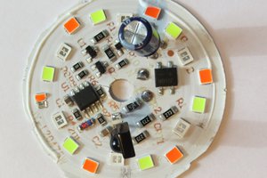
 Tim
Tim
 w_k_fay