Ken Yap
-
Another use for the expander board
03/29/2024 at 12:31 • 0 comments![]()
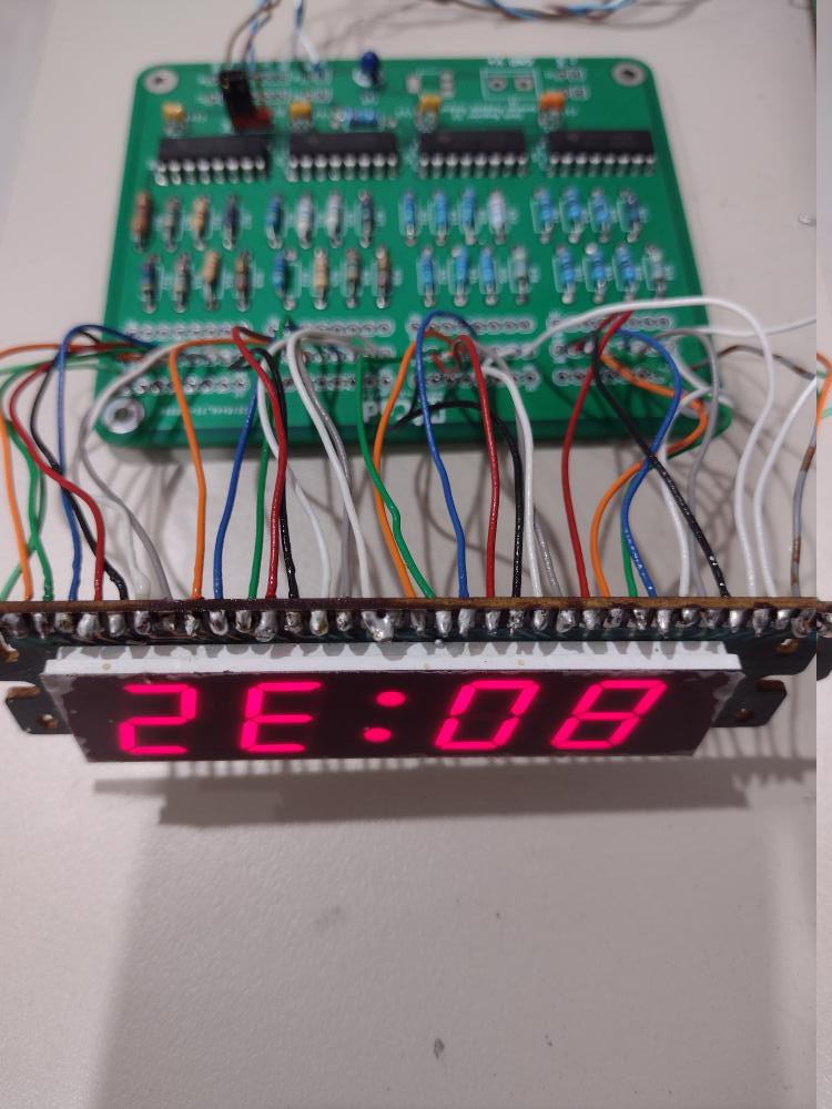
I've put another of this board to use to drive an alarm clock display. My bedside radio/alarm clock is failing so I'm replacing the dedicated clock chip from the 70s in it with a modern MCU based design. I have a second copy of the LED display used there with all segments brought out to the connector. The display is dim despite a current of about 5 mA per segment due to the era of the LEDs but that's ok for a bedside clock; you don't want to be kept awake by the light.
The display is being tested so it's upside down. But even if you flip the display mentally, you'll notice that the time is strange, it reads 80:32. The reason is the test program is sending out the serial data most significant digit first, so the correct time is actually 23:08. It's just a test program so I'm not bothered as long as it proves that the display is working.
I'll write up the alarm clock project when it's done.
-
SMT version published
07/20/2022 at 21:22 • 0 comments![]()
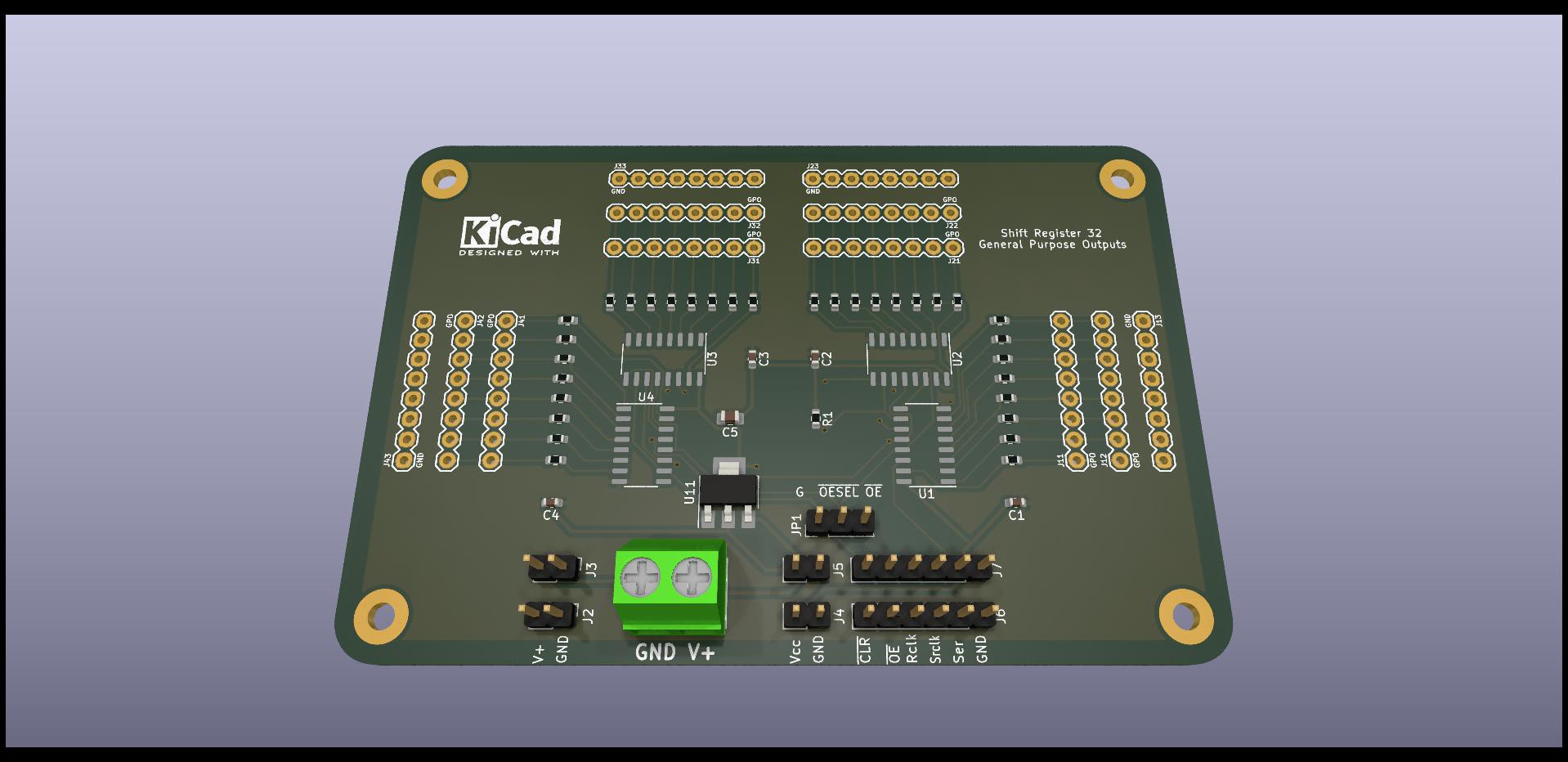
I have published a SMT version of the board, ready for PCB assembly to avoid hand soldering a whole heap of resistors and capacitors. It follows my investigations into the cost. You can find the link to the Github repository in the link section.
This version is not tested, as I currently do not have a need for more expanders, as I still have a lot of the THT version, used for example here. However the circuit design is unchanged, only the components have been rearranged on the board, and BoM and CPL files generated for a sample manufacturer, JLCPCB. So it should work, touch wood. I'm publishing it in case someone can use the design.
3 line to 32 line output expander
Expand 3 digital output lines to 32 with shift registers