Close
0%
0%

Hexapod

This is my long-term hexapod project. It will be under development and improvement for few years.

Similar projects worth following

This hexapod is my long-term project. It will be under my development for few years. I will try to update my progress as frequent as I could. The reason why I pick hexapod is because I would love to work on legged robots more than on wheeled robots, even though it is a lot more complex. I will try to apply every new thing that I could learn about robotics on this project. Hope it could grow along with my robotic career

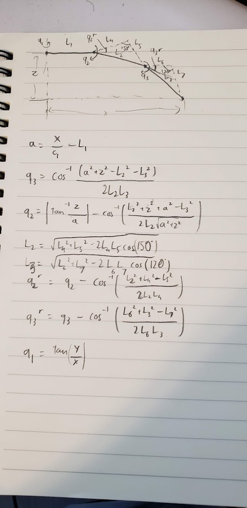
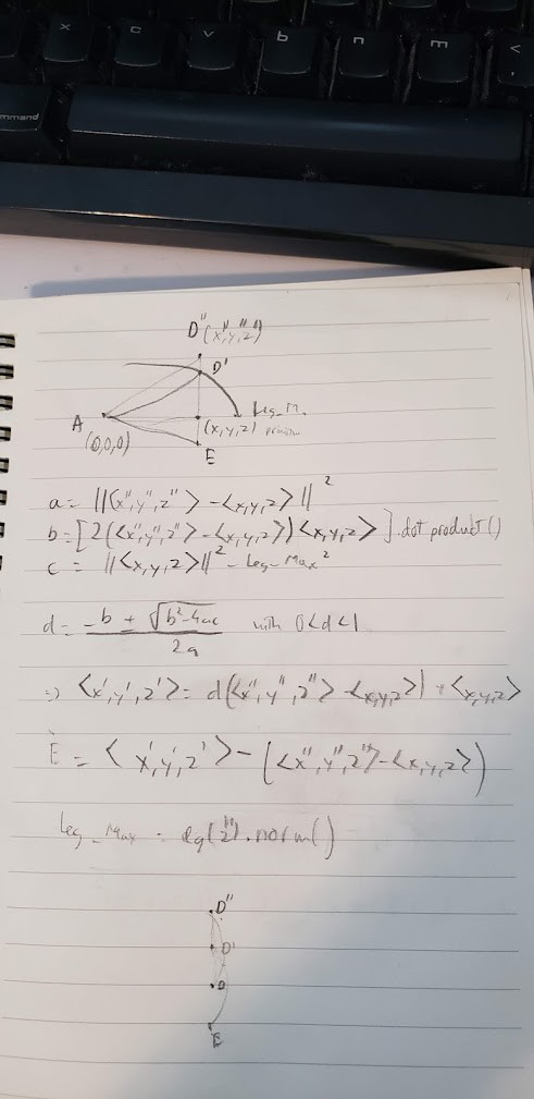
1st version: Hexapod will be controlled by laptop using keyboard through ROS. The hexapod will be controlled with 6 DOF input, and concurrently using rplidar to draw a 2D map

Here is my github code: Uchiwuwu/Hexapod (github.com)

Hexapod.7z

My hexapod 3D model In case if the file isn't working https://drive.google.com/drive/folders/1NfmsOHHxJBoa843uozik0hz9dXtL-TVG?usp=sharing

7-Zip - 13.05 MB - 03/17/2022 at 17:46

Download

  • 18 × Dynamixel AX-12A Servo Motor
  • 1 × Dynamixel U2D2+Powerhub board Motor Controller
  • 1 × Raspberry Pi 4b Microprocessor
  • 1 × 1300 mAh battery Battery for motors
  • 1 × Portable Battery Battery for other components

View all 9 components

  • First Update

    Uchiwuwu03/17/2022 at 20:36 0 comments

    Currently, I'm debugging my code. You can take a look on my code in the Detail part. The current plan is to debug my code asap and then I can work on adding rplidar for drawing map. Then I will make a video footage when my hexapod draws a map of my room.

View project log

  • 1
    Components

    Dynamixel AX-12A:

    The biggest problem on controlling hexapod is controlling its leg, and that is what makes choosing motors the hardest job for component part.  What I'm planning to do in the future for controlling this hexapod is using dynamic torque control theory. Thus, I would want a motor that could be controlled with torque and having encoder for angle feedback. DC motor with encoder tagged along could be the choice, but most of DC motors with encoder I found on the market have very low CPR (usually around 64). For those with high CPR, they are pretty expensive, compared to my current budget. Step motor could also be an option, but the price is very incompetent to me. So I picked dynamixel ax-12A as my motors. It is more expensive than other servo on the market, but it could give angle feedback with 0.29 degree resolution, and more importantly, it could also be controlled with torques and velocities, which makes it so different with other servos on the market. The problem with dynamixel servo is that it is controlled by TTL signal, instead of PWM signal. Thus, I would need something to convert my pwm or analog signal to TTL signal.

    Dynamixel U2D2:

    Because the dynamixel servo can only be controller with TTL signal, I need to make a circuit that can convert full-duplex uart signal into half-duplex uart signal. Here is the online instructions I found: How to Drive Dynamixel AX-12A Servos (with a RaspberryPi) : 6 Steps (with Pictures) - Instructables. Fortunately, instead of making the circuit, scaling it up for 6 legs and creating a PCB, so it could fit in my hexapod body, I could just use dynamixel U2D2 to control with usb port. 

    Raspberry pi 4b:

    Arduino can also be used as microcontroller. But due to the amount of my external library used in my code, I would want to use raspberry pi for current and future functions.

    Force sensor:

    Normally, people would use momentary push button switch for hexapod legs to detect the ground. But in here, I would want to use FSR instead. Besides of detecting the ground, it could be used to measure the force the legs applying on the ground. For future plan, I will use it to see if I can make use of its force data to move on different surface types of terrain. But for now, it will be used as the momentary push button to detect the ground only. The signal delay due to the gap between force sensor and the leg tip in my model can be solved by modifying the tip coordination in calculations.

    Other components:

    Battery is used to power my motors. The portable battery is used to power other components.  An Adafruit 16 PWM pins is used for additional voltage/ground pins for my raspberry pi. It could be replaced by any simple PCB for powering. I picked it because I had it for my old projects and it was unused at the moment I was picking the components. rplidar is used to draw a 2D map of my room with Rviz.

  • 2
    Forward and Inverse Kinematics

    Here are my forward kinematic equations for swinging and standing phases:

    Here is some of my notation explanation. P_A-B is the relative position of point B, respected to the frame of point A. N is the reference frame of the robot, initially at the center of body of the hexapod. R is the rotational matrix. N-O_R is the rotational matrix of frame N to frame O. I'm sorry for my bad explanation.

    In the swinging phase, the leg will rise and lane on the ground with new position. The new position will be calculated in the method that when moving the leg back from new position to previous position, the body of center will be shifted and drifted as the desired 6 DOF input. In the standing phase, the leg will be moved and continuously contacting with the ground. The method for standing phase is bit different. When moving toward or backward the new position, the COB will be shifted and drifted as the desired 6 DOF input. The equations to calculate the new positions in both phases are shown in the picture above.

    Here are my inverse kinematic equations for leg angles calculations:

    c_1 is cos(q1). X, Y, Z is relative positions of the tip of the leg, which will be calculated by forward kinematic equations discussed above. From this, desired angles to the new positions can be calculated.

    Additionally, there is a problem that the desired positions are out of the leg workspace. This problem could be possibly faced with when manually inputting 6 DOF desired displacement for hexapod. There are quite a few solutions for this problem, such as confining the positions, drifting positions back into the workspace, or looking for other possible positions, etc. In here, I will show the drifting solutions I used for this problem. It can only partially solve the problem above.

    A is the joint position between the leg and the body. D'' is the next step position of the tip and D' is the shifted new positions. Leg_Max is the max norm of the leg vector from the joint to the tip. This norm equation will be in term of Z (next desired z). E is the next of the next step position (not necessary for pre-calculating). For now, these equations only work well with 2D problem (the ground is paralleling with the hexapod). I will try to work on this solution in the future to get a generalized equation or look for a better method for this problem.

  • 3
    Control Diagram

    Here is my control diagram:

    It is very straightforward to my code. For the code, I would want to use thread to concurrently run calculations and commands for 2 leg pairs. It would be better if each leg can be controlled by 1 thread, but due to hardware limit, I can only use a thread for each pair. In the future, when dynamic theory is applied for torque control. I would need a better thread utility.

View all 3 instructions

Enjoy this project?

Share

Discussions

Similar Projects

Does this project spark your interest?

Become a member to follow this project and never miss any updates