0%
0%
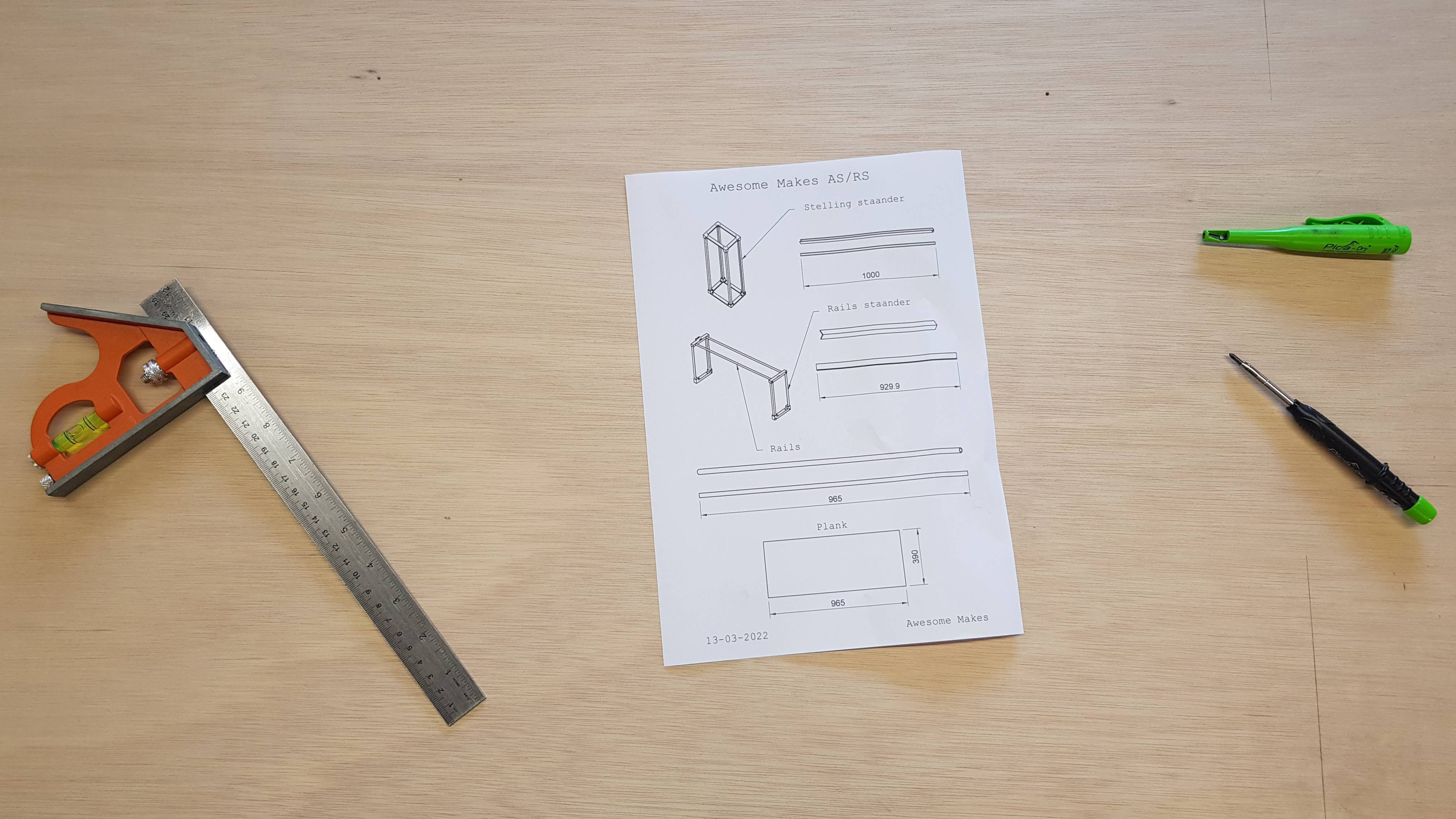
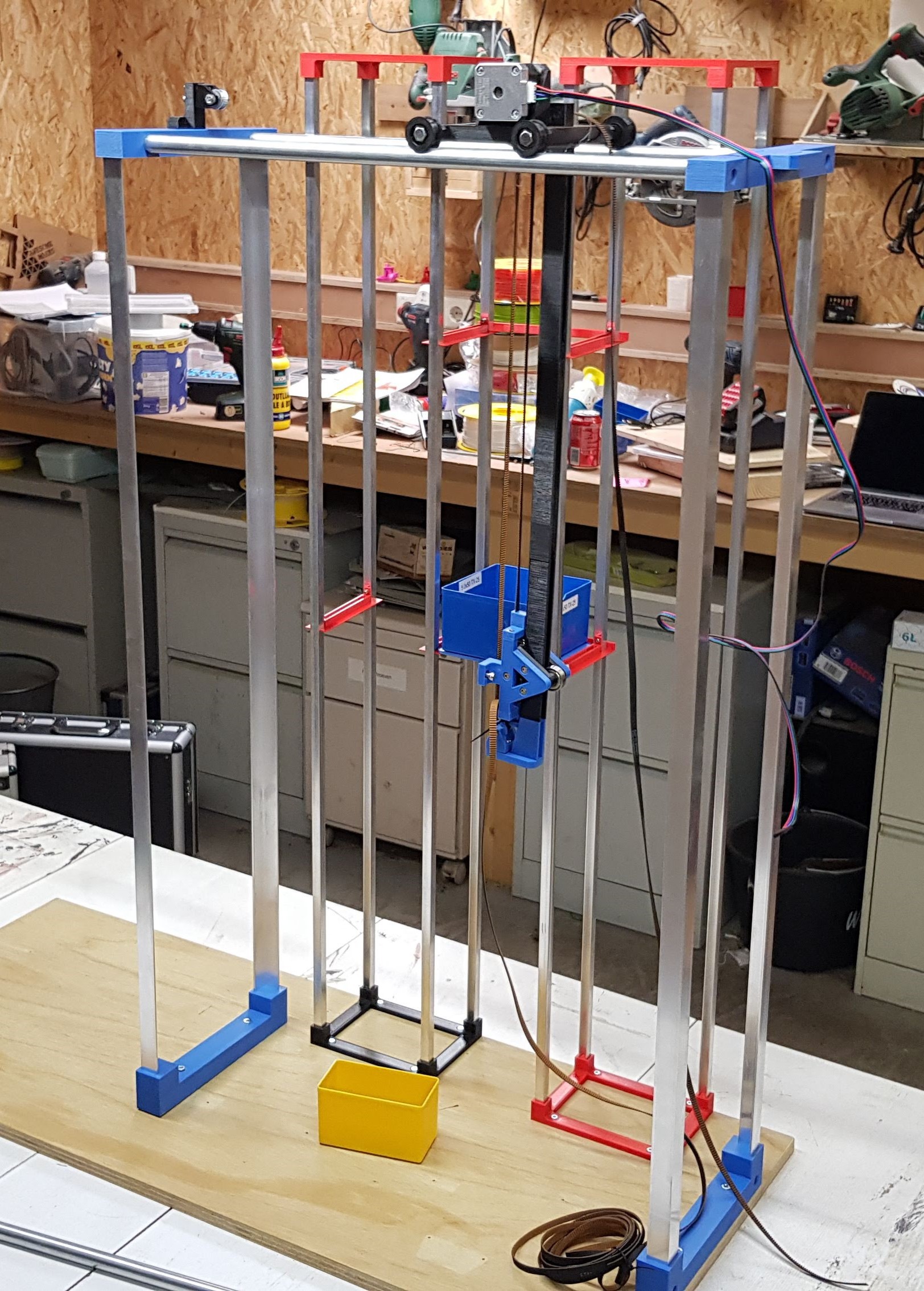
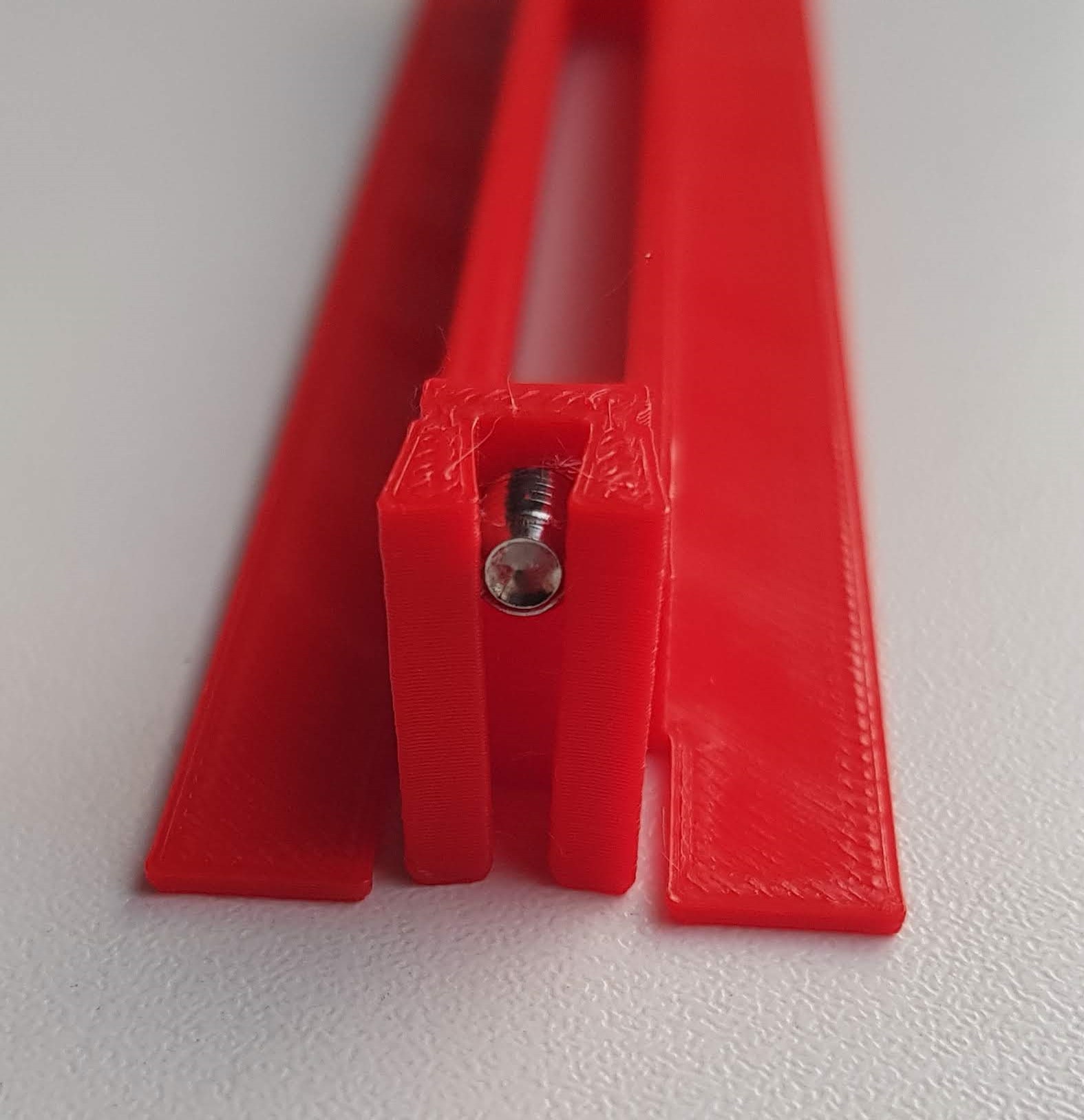
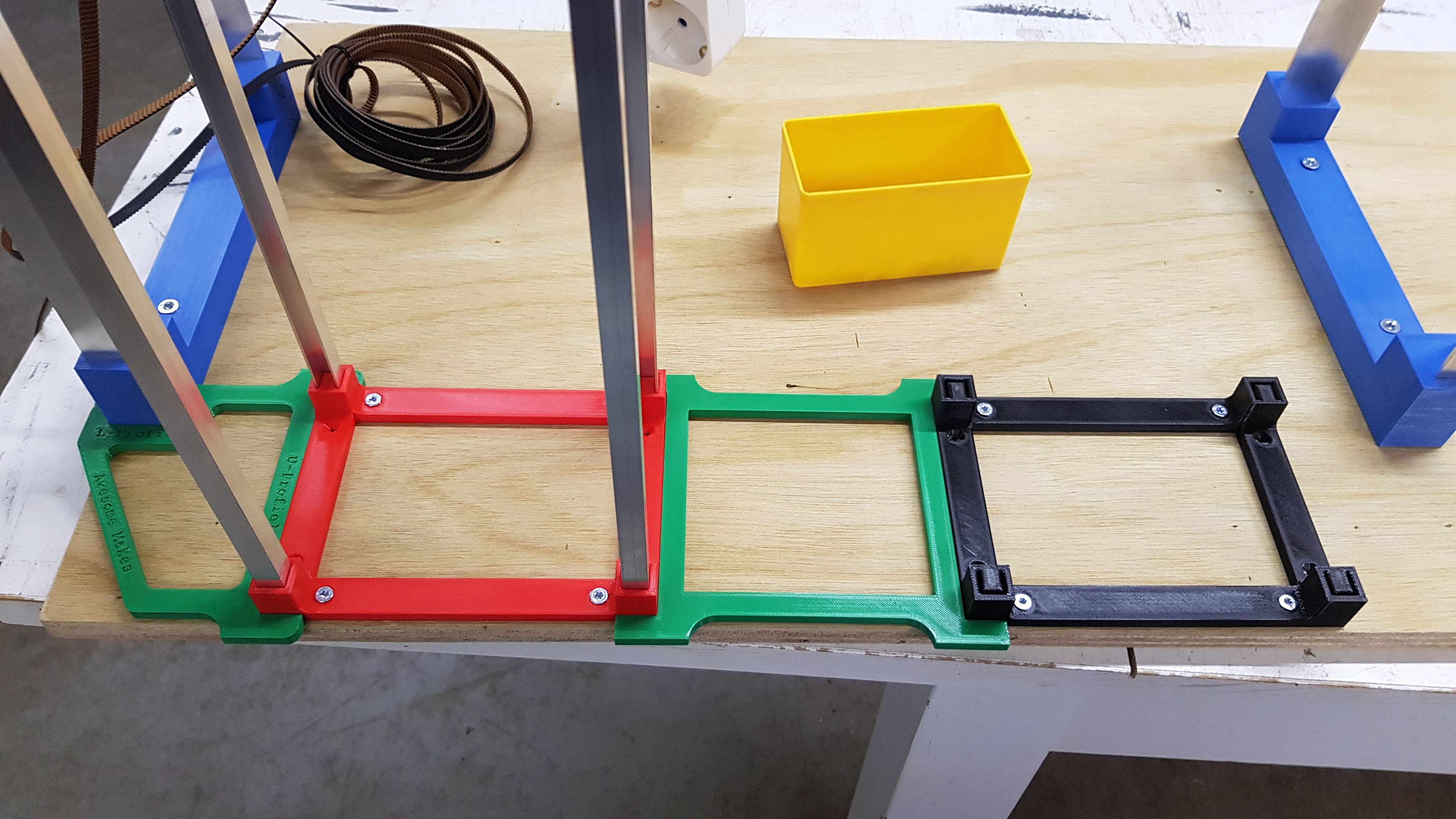
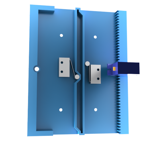
Automated storage and retrieval system
A system that automatically stores and retrieves small plastic bins. Made with 3D-printed parts, aluminum, stepper motors and Arduino
 Awesome Makes
Become a Hackaday.io member
Already have an account? Log in.
Just one more thing
To make the experience fit your profile, pick a username and tell us what interests you.
Pick an awesome username
hackaday.io/
Your profile's URL: hackaday.io/username. Max 25 alphanumeric characters.
Pick a few interests
Projects that share your interests
People that share your interests
 Ossum
Ossum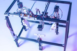
 Patrick
 MatterHackers