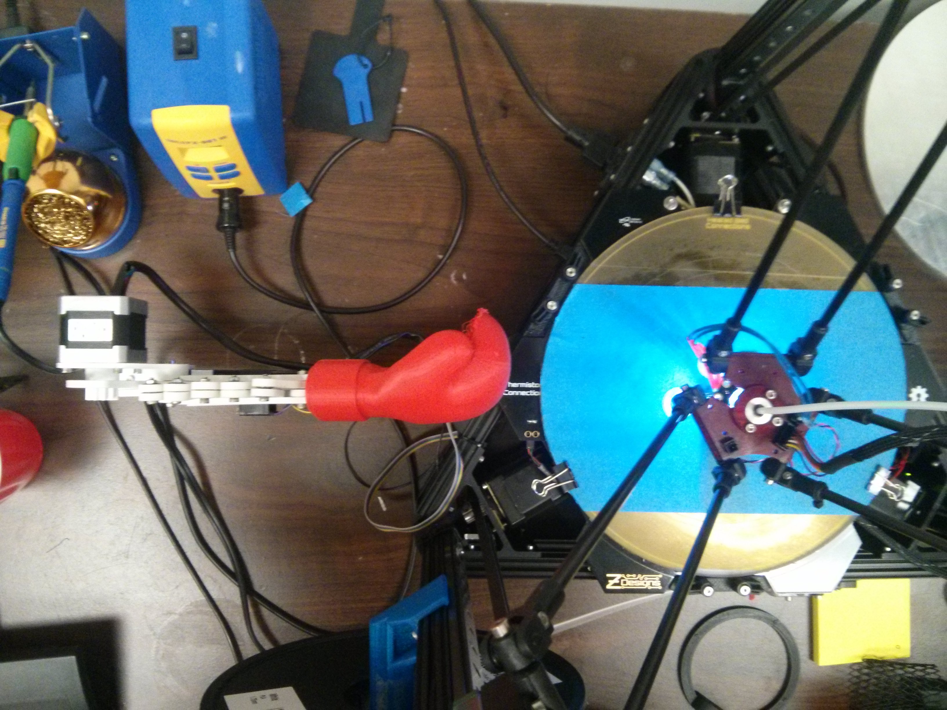
Its made entirely from printed parts and things we had laying around. The printer being victimized is an OpenBeam Kossel Pro.
Mechanics
I started off by quickly designing some linkages in Solidworks. The holes fit some little ball bearings we had laying around. Everything is held together with M3 bolts. We had an assortment of different sized bearings, so I had to design parts with a couple different hole sizes. All of the ones posted online, though, are made to fit 9.5mm outer diameter bearings. The holes also include an extra 0.3mm to account for the tolerances of printing.
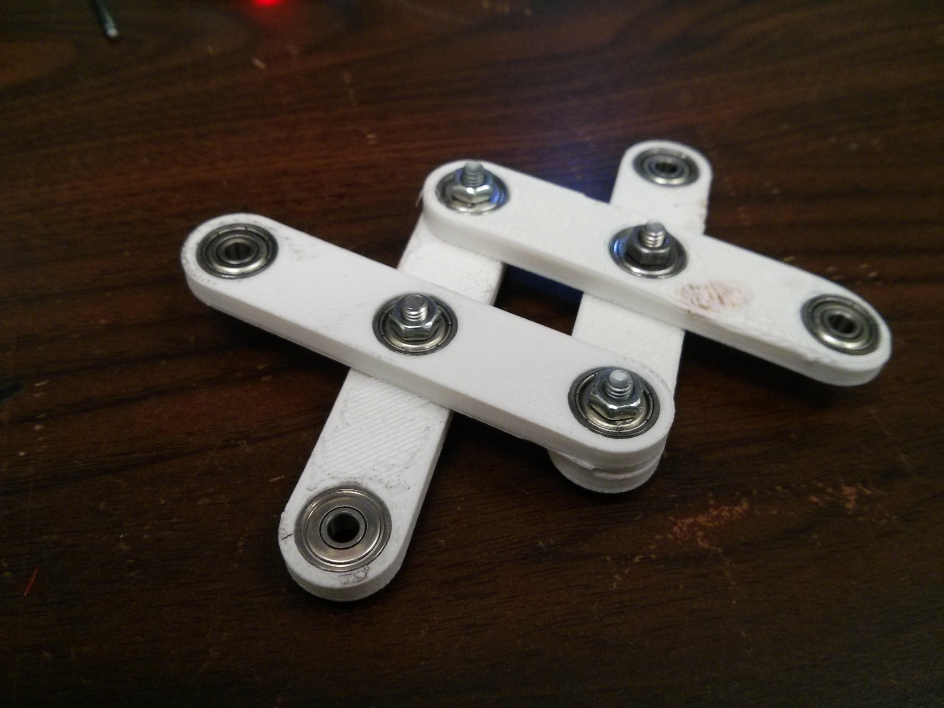
This was a fun project because most components took less than 30 minutes to print. I could be designing the next thing while the last thing was printing. There was no waiting. In some cases its better to plan everything out at the beginning before you build it, but it can be more fun to just dive in and figure things out as you go along. That's what I did with this project. I ended up with a lot of trashed parts, but who cares.
Everything was printed in PLA since I was not worried about anything getting warm. Print settings:
- 0.2 mm Layers
- 2 Perimeters
- 30% Infill
In order to actuate the scissor mechanism, I added a gear to the end of one of the linkages. I also found an old stepper motor to drive it. I could have used a hobby servo, but the stepper is what we had and its got more torque anyways. It also conveniently had a small gear already on the shaft.

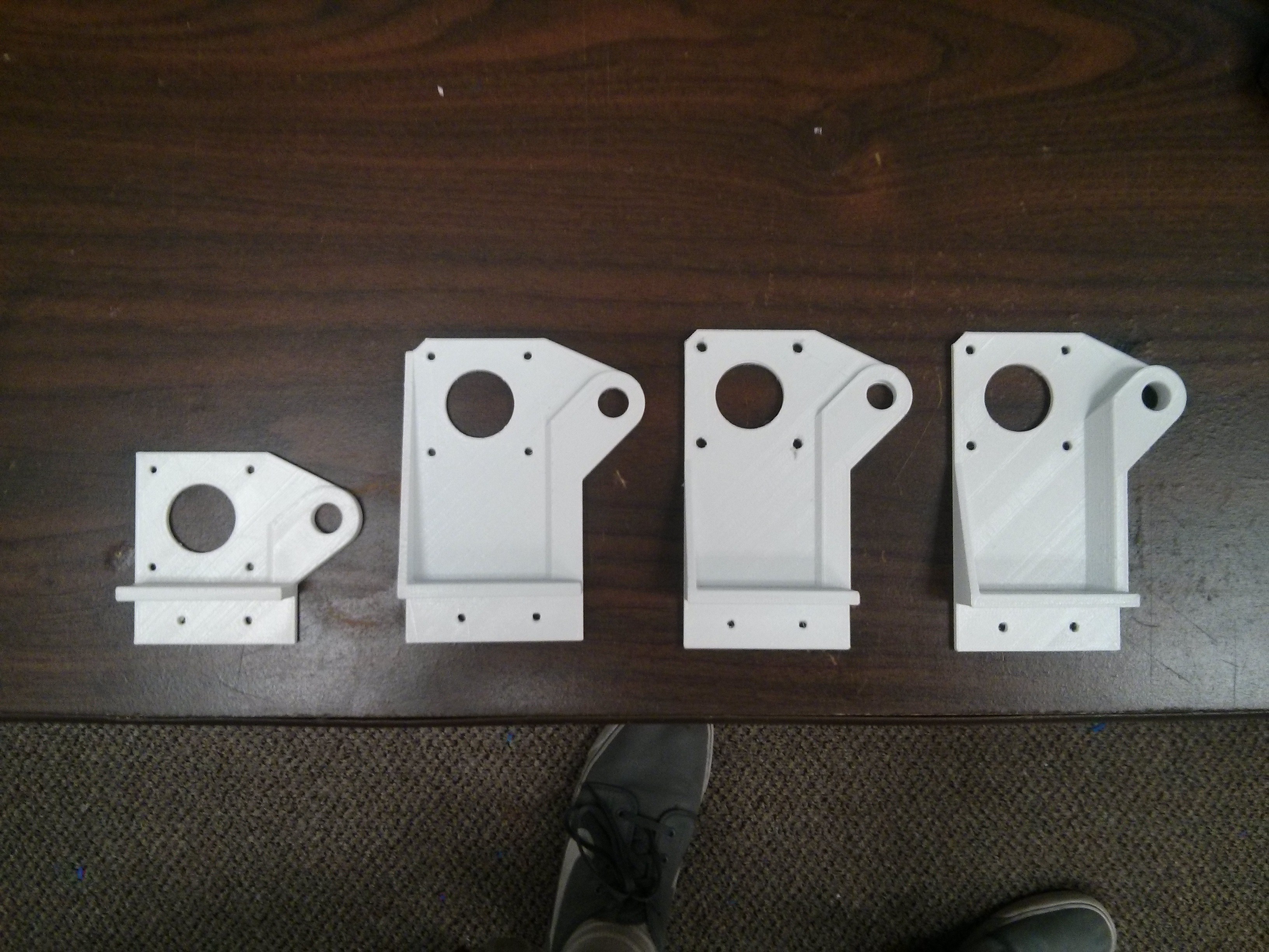
This is the bracket I designed to hold the motor and everything. The plan was that the entire device would jut out from the side of the printer, supported by a length of OpenBeam. As you can see, engineering is an iterative process.
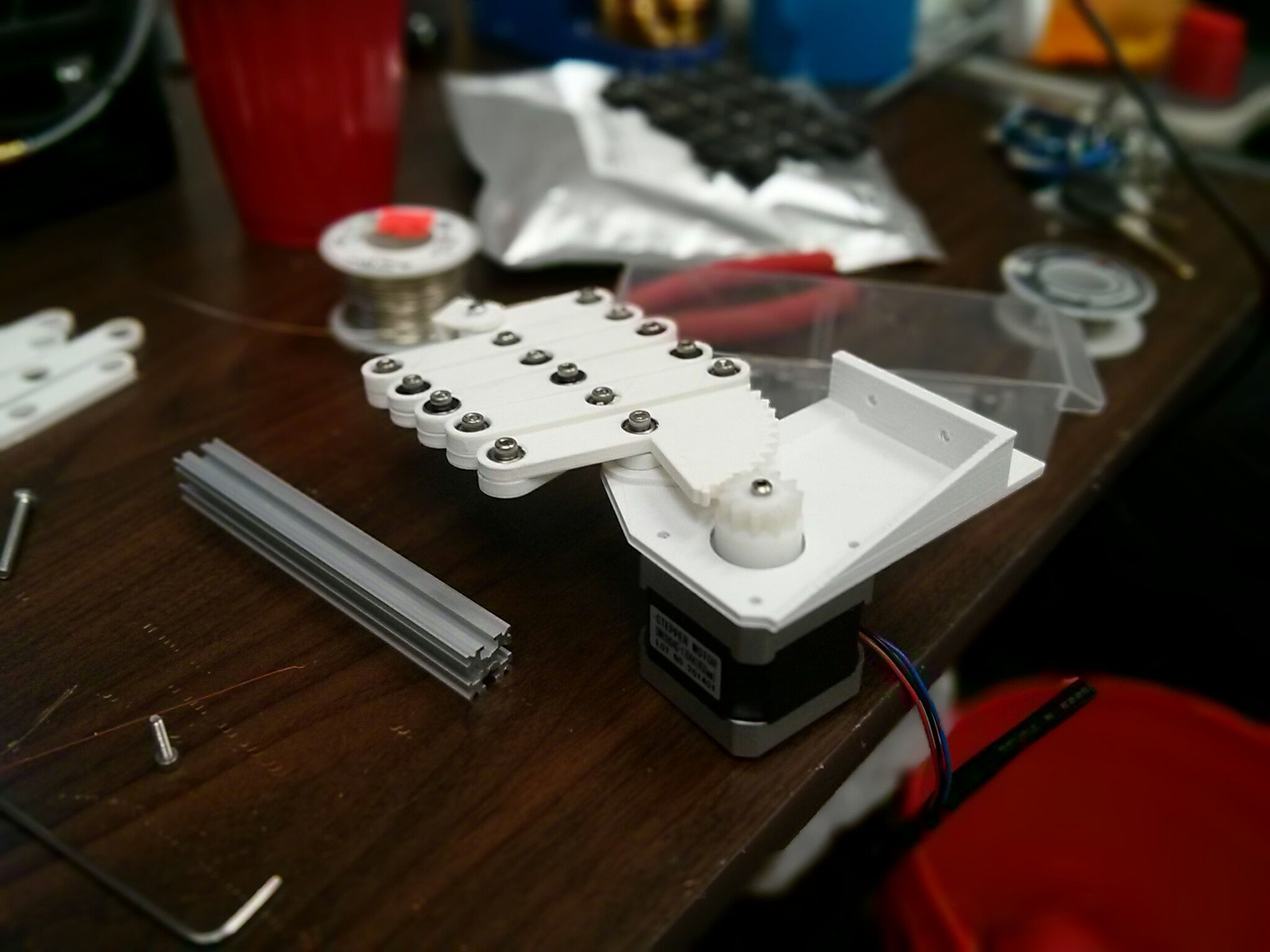
At this point it became apparent that only driving one linkage wouldn't work. The entire assembly would just rotate down instead of extending outward. Both of the end linkages need to be forced together or pulled apart in order for the mechanism to work. I added a second gear with inward facing teeth. This way it would be driven in the opposite direction, forcing the linkages together.
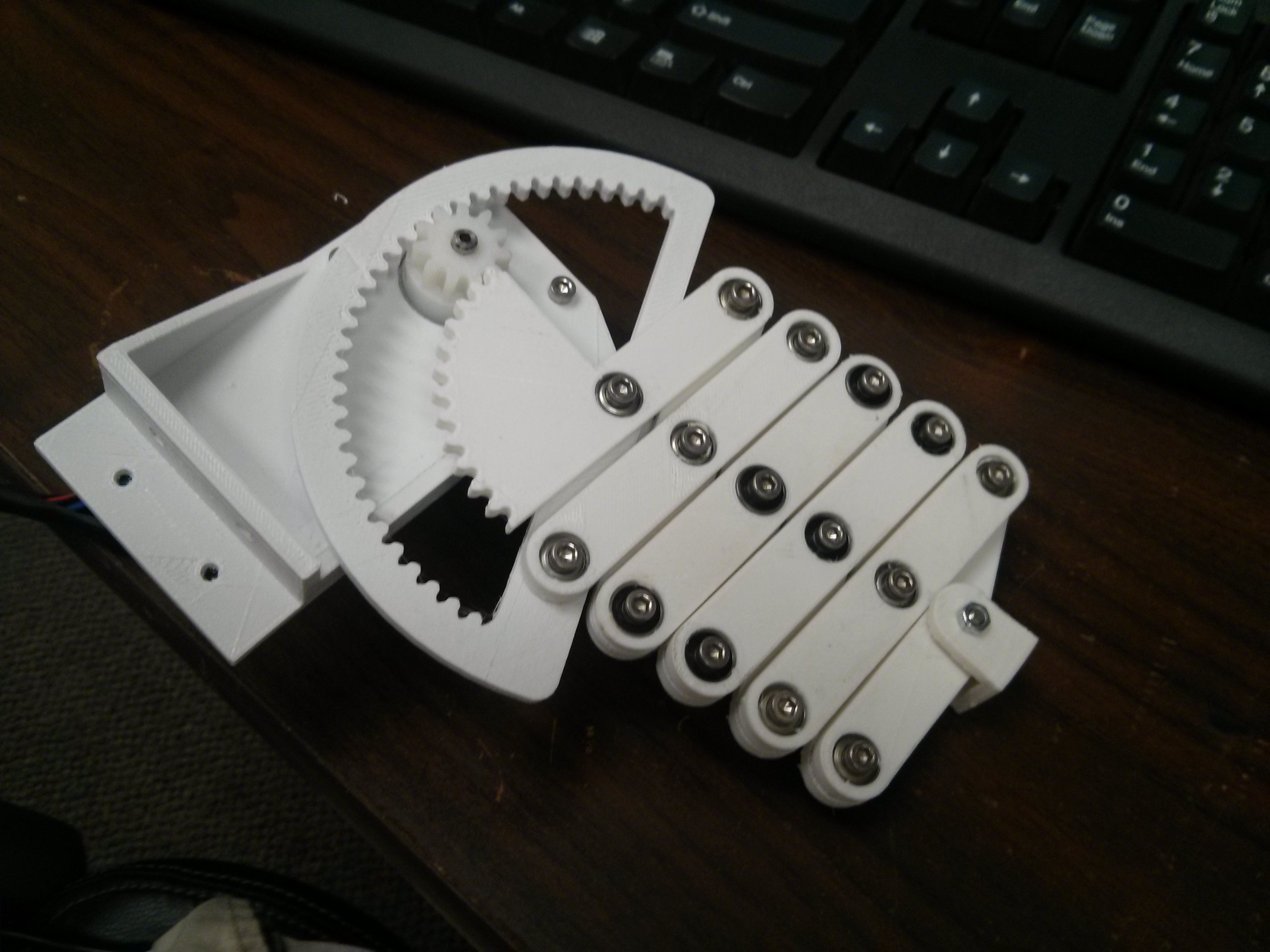
Since the gears have different radiuses, there are slightly different gear ratios and one linkage moves slightly farther than the other. This makes the whole thing rotate downward a few degrees when it extends. Oh well. Its good enough.
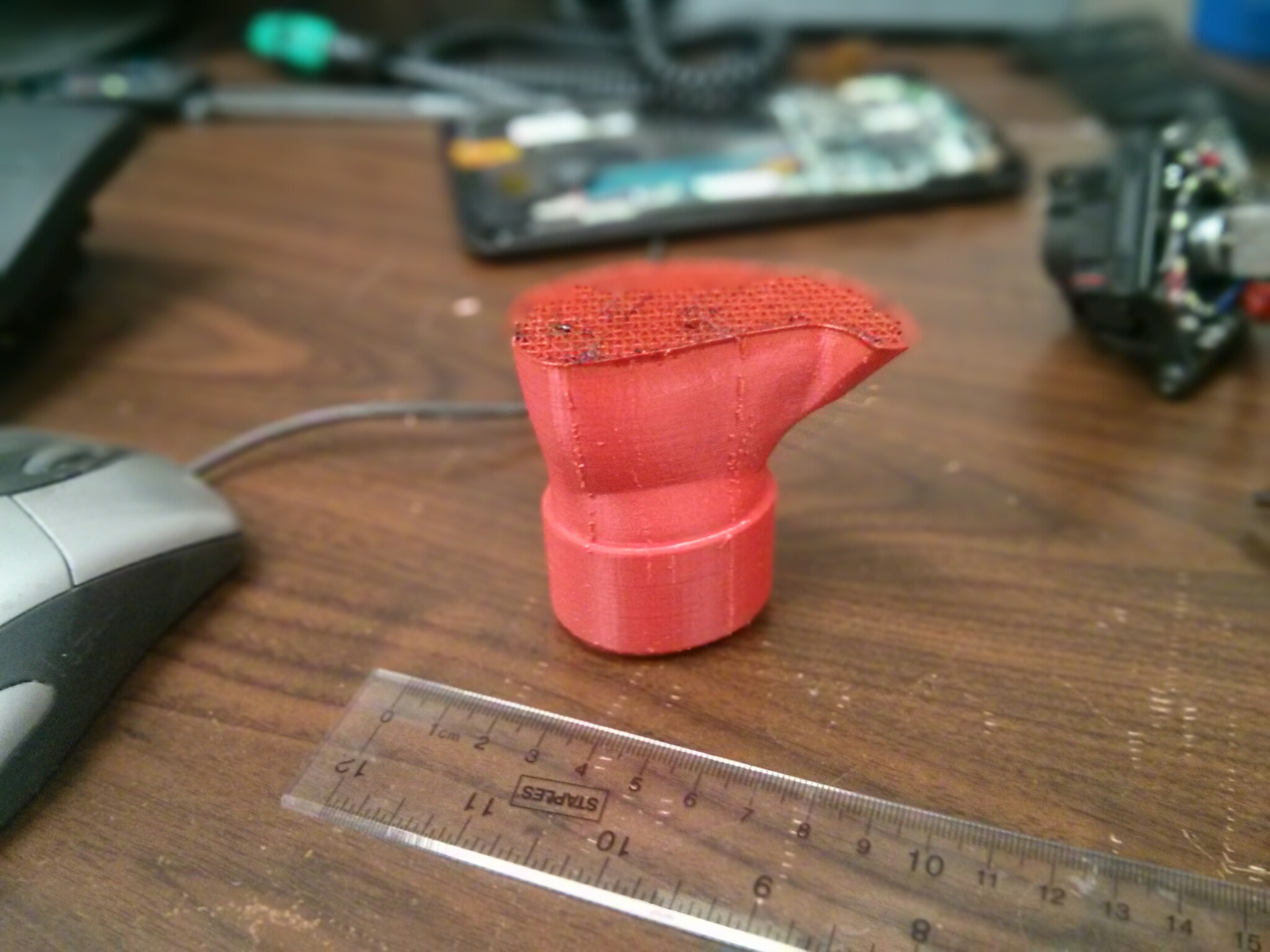
The boxing glove model was found through googling and I modified it in Blender with a square hole in the bottom to connect it to the arm. This glove turned out to be the most difficult thing to print. Not because it is a complicated shape, but purely because of a series of unfortunate coincidental issues with the printer (some of which involved fire). When it finally did print, the support structure under the fingers failed, so it doesn't have fingertips. I decided I don't care since you won't see that side much anyways.
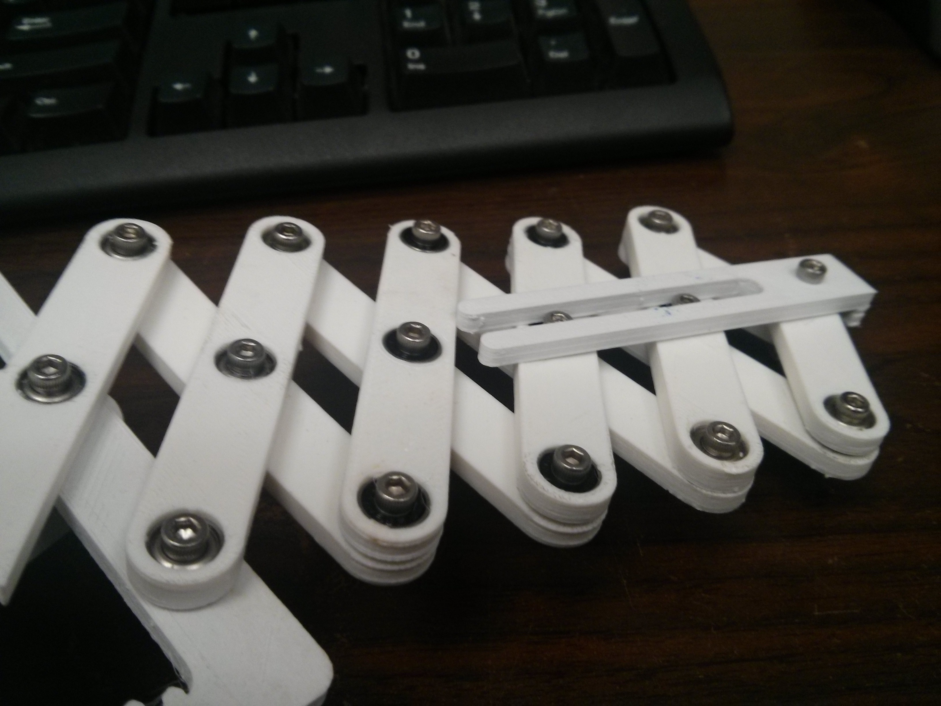
This is when I ran into the next problem. How do you keep the boxing glove horizontal? I designed a fork shaped thing that would slide over the bolts in the center of the linkages. This makes sure that whatever is attached to the end stays parallel to the mechanism.
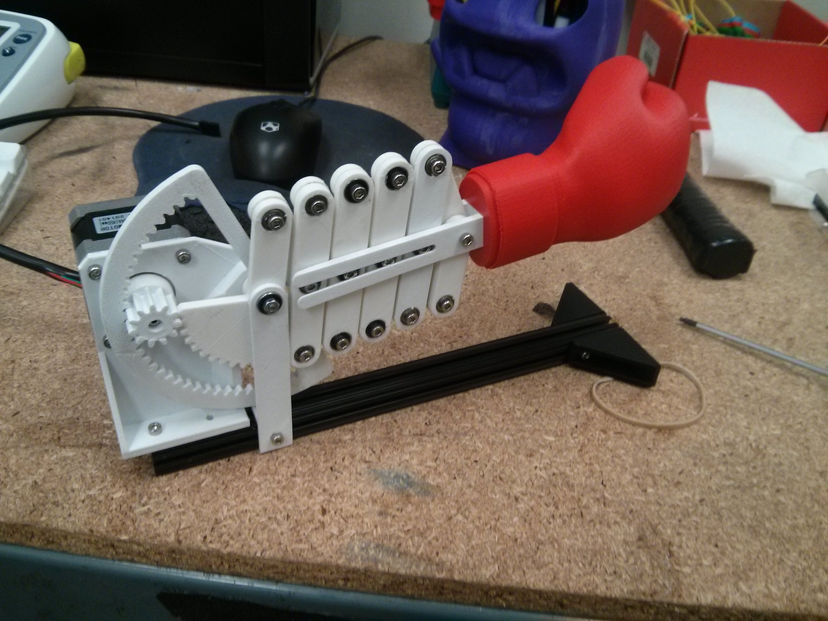
Last step was to attach the beam to the bottom and bolt it onto the side of the printer.
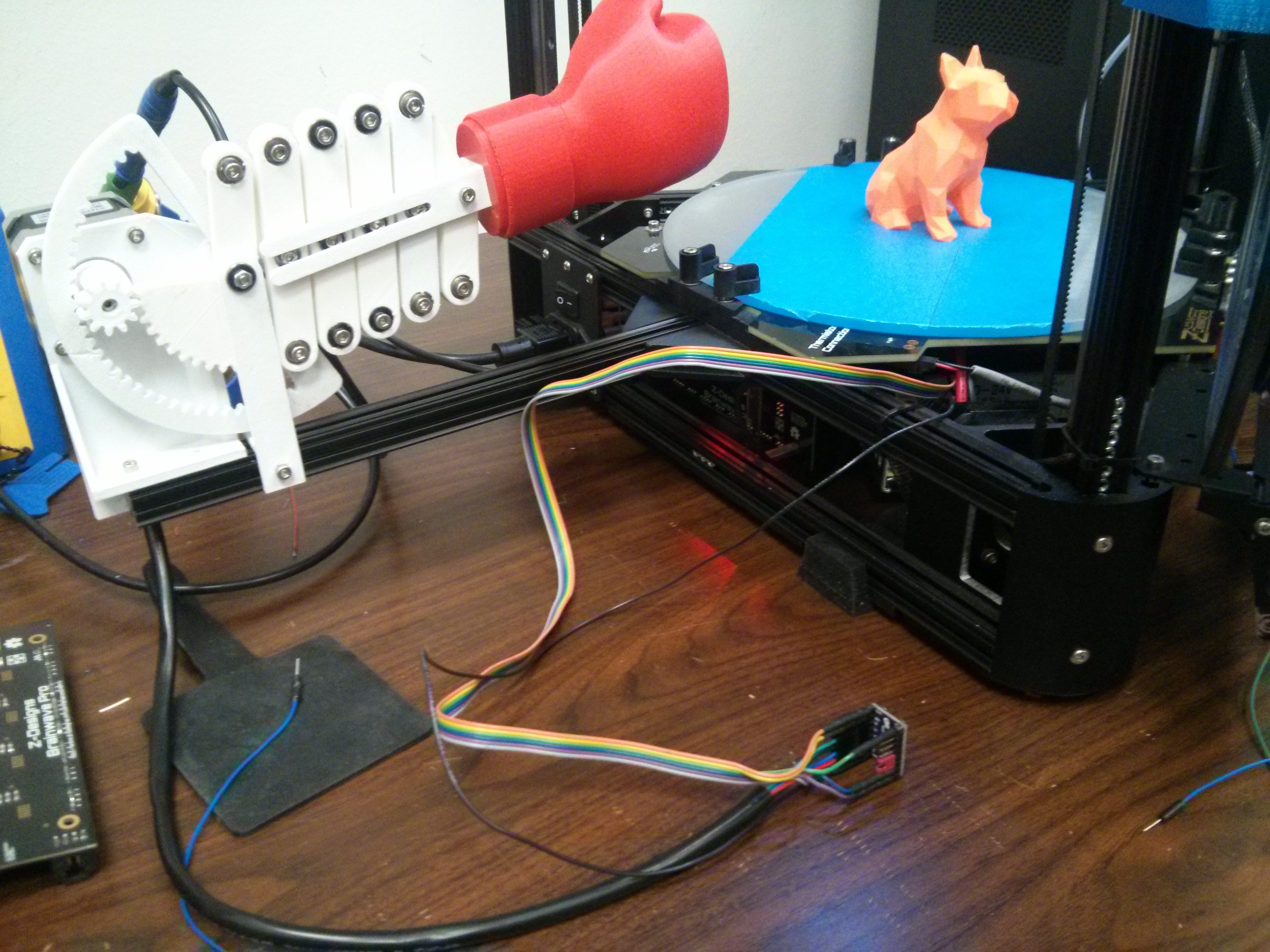
I had to design some corner brackets as well in order to connect the beam to the printer's frame. The bed is in the way so I could not use the official OpenBeam T-Brackets. Fortunately I remembered to put some extra nuts in the beams when I was building the printer. Because the thing is mounted perpendicularly on one side, it punches the objects straight into the tower on the opposite side. Eventually I will make some 30 degree / 60 degree corner brackets so it will punch in the right direction.
The 24 cm beam is just barely long enough. The print head narrowly misses the glove while doing the auto-calibration routine and bumps into it a little bit when printing all the way out to the edges.
The finished product:
Electronics
Wiring was pretty straightforward. I salvaged an old Pololu stepper driver from one of our spare...
Read more » MatterHackers



 Tyler Anderson
 Ossum
Ossum
 Chris
Chris
Thats just brilliant haha, well played, skull for u