 DIY GUY Chris
Supplies


The needed tools:
- Solder Plate (You can use the Uyue 948S+ model)
- Solder Iron
- Low temperature Profile solder paste
- Solder paste deposit spatula
The needed software:
- Altium designer as ECAD for PCB drawing
- Solidworks as CAD for housing designing
- Cura as slicer for 3D printing
- Arduino IDE
Note: You can download the necessary CAD files from article links
Step 1: Circuit Design


First and most important step is the selection of the appropriate components to establish a working circuit design. Since I'm dealing with the RP2040 MCU by RaspberryPi foundation then I moved to their website where I found an interesting link document to the recommended circuit setup, you can check the document link by clicking on this link.
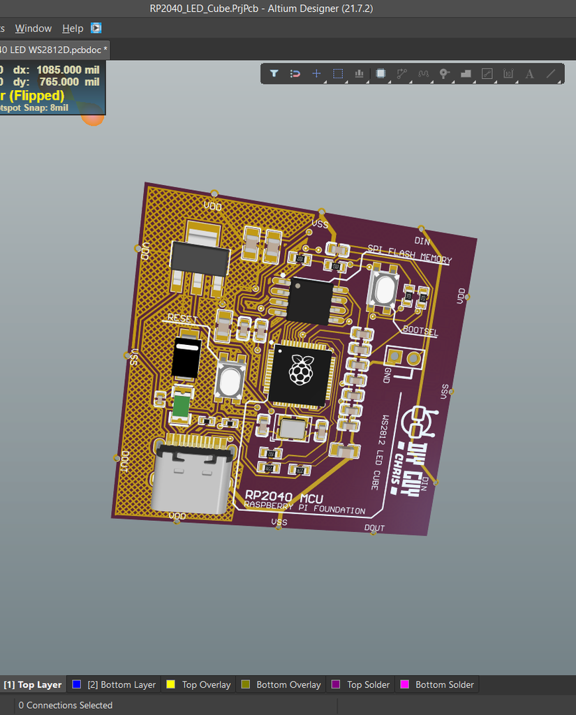
I then followed the recommended setup to create a circuit design on Altium designer (I attached a screenshot of the Schematic), a attached supporting PDF file of the circuit schematic is available below.
I divided the schematic to four main blocks:
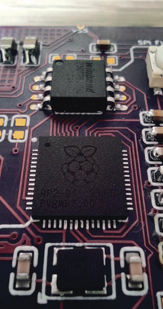
- The RP2040 Setup:
In this block, you can visualize the needed components around the micro-controller, I highly recommend that you don't ignore the decoupling capacitors for the power lines of the MCU and keep them closer to the power pins in your PCB design (recommended 100nF capacitor per power pin).
- The Memory Chip:
Maybe this micro-controller looks a bit different then the other ones since it needs an external memory chip where we load the program code, that's why I use a QSPI memory chip (recommend W25Q128JVS device).
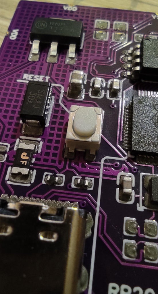
- The Voltage regulator:
This MCU needs a 1,1V generated internally by the MCU itself and a 3,3V that has to be provided externally through a voltage regulator and that's the use of the voltage regulator on my schematic.
- The USB C:
I got several requests on "what is the best setup for USB C connector for serial programming" and here I used a Type C connector so in case you are willing to use this Connector in any design of your designs then you can follow the Setup of the USB C block on my schematic.
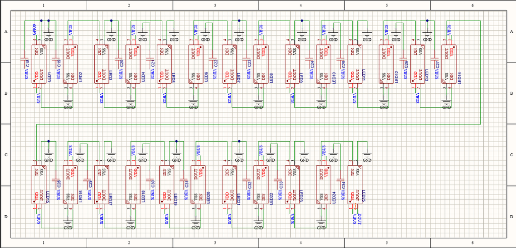
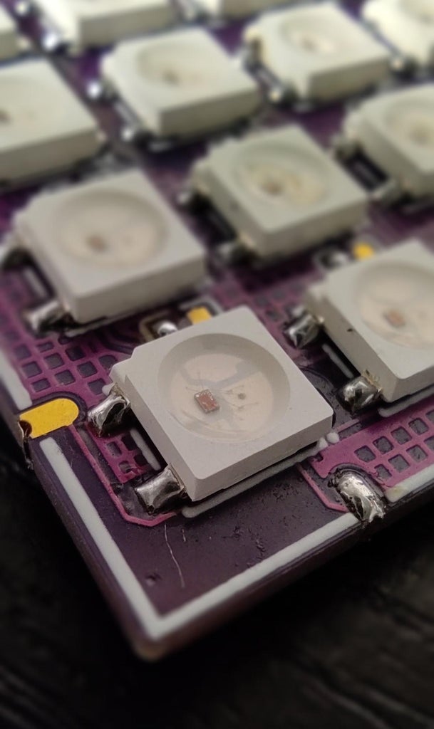
I then placed 25 RGB LED of the WS2812 type wired in series and accompanied with some 100nF decoupling capacitors.
About the PCB design you can decide the shape of your choice, in my case it is a cube shape that's why all the Cube pieces has to have a rectangular shape (40mm x 40mm) you can go for a bigger size but the 40x40mm is the suitable size to equally distribute the RGB LEDs.
Note : you can download the PCB design GERBER files from this link
Step 2: Parts Assembly


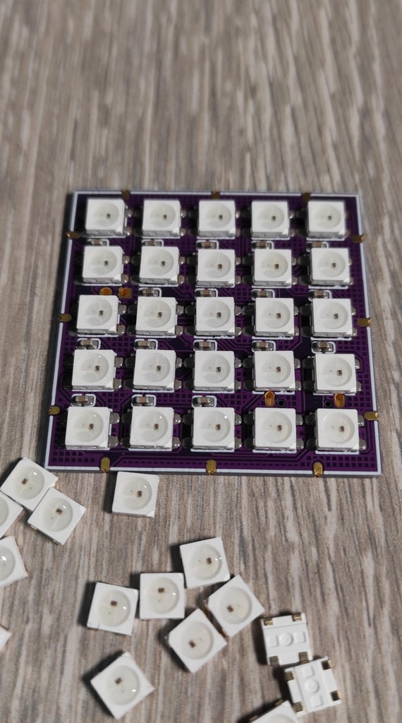
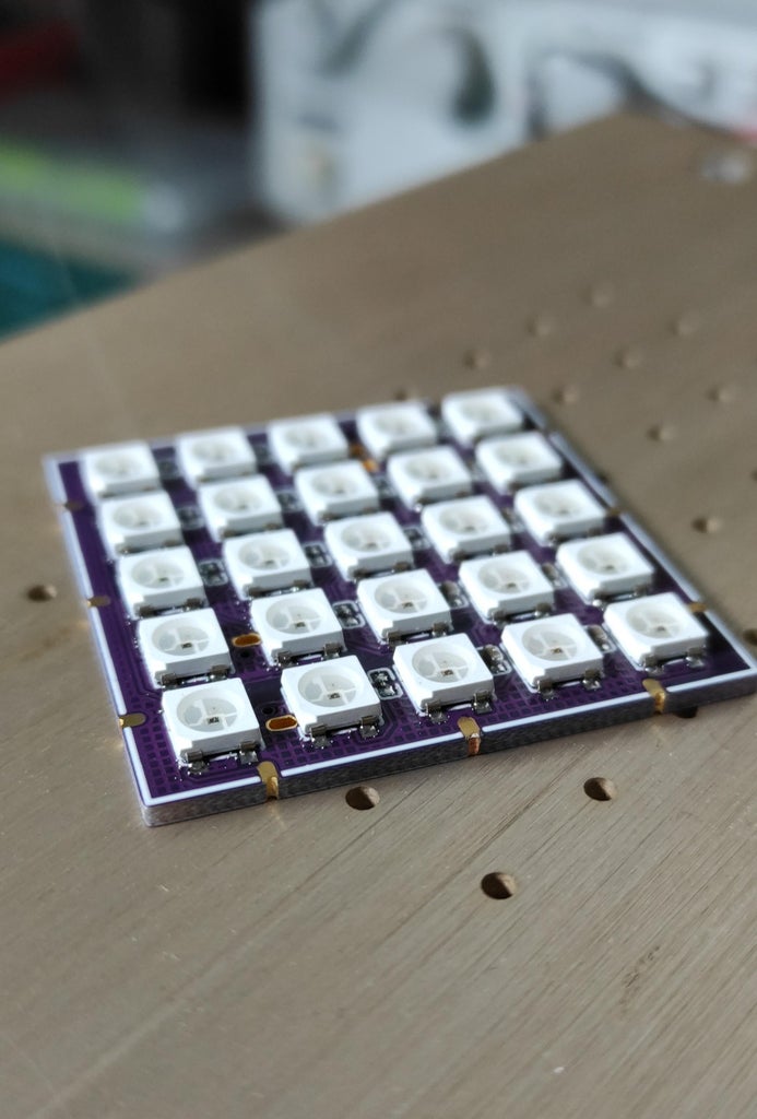

After getting the PCB design produced and delivered then all what I need is soldering the electronic components for the top and bottom sides of one single piece then I solder just the RGB LEDs in the bottom side of five pieces, all in all we have six pieces creating the cube shape. I used the Stencil that I order alongside with the PCB and this will help to equally distribute the solder paste on the PCB spots.
Probably some of you guys are not familiar with PCB assembly, not a problem because you can order the design fully assembled by any PCB manufacturer of your choice as long as you have the GERBER file BOM and P&P files which I already added them to this project. (the GERBER could be downloaded through this link)
I use Hot plate to assemble the Cube pieces, I used a low temperature solder paste due to the low temperature of my hot plate.
Note: don't forget to clean the flux from your assembled boards after finishing the assembly
Step 3: Code Preparation
The biggest advantage of the use of this RP2040 MCU is that you can program it through Arduino IDE (in addition to its cheap price) so I moved to Arduino IDE and brought the Neopixel library that allows me to explore some preset APIs to control the WS2812 LEDs through one output pin, yes, this is the positive point of the use of these RGB LED type, you can put all them together in series and get them all controlled through one single output...
Read more »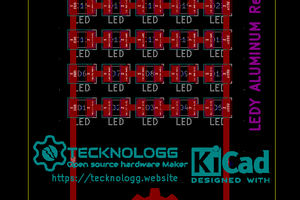
 Chromico
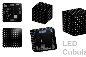
 Jack Flynn
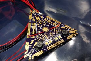
 slisgrinder
 Jana Marie