Close
0%
0%

BLUETOOTH MUSICAL PCB TESLA COIL

A bluetooth musical tesla coil, but fully on a pcb, NO COILS, and also only powered by one 12v supply.

Similar projects worth following
A musical Tesla coil etched on a pcb. Circuit also includes boost converter in order to achieve big arcs with only 12v.

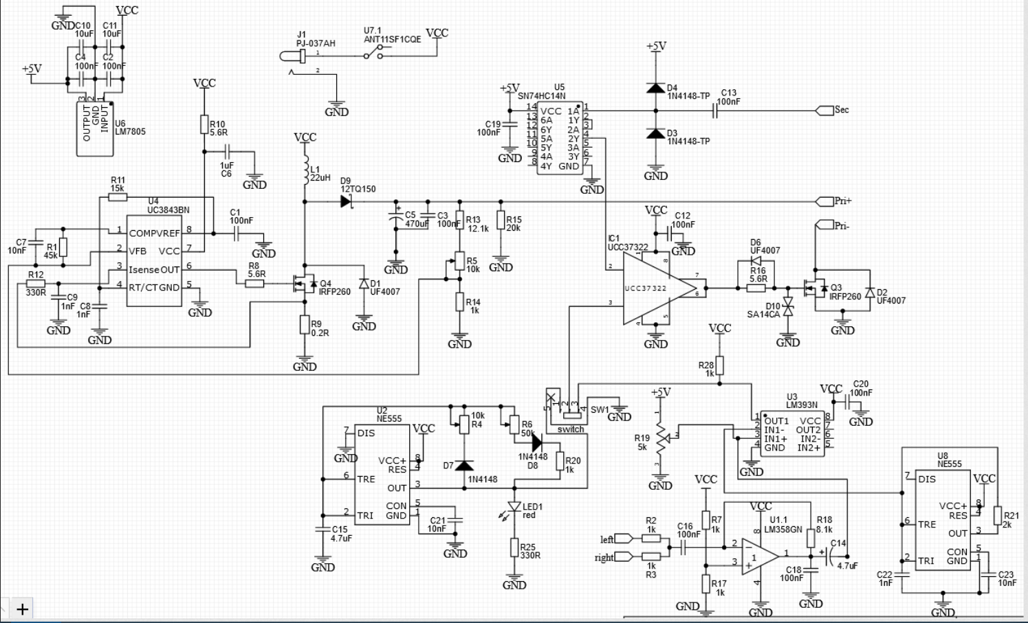
This isn't a regular tesla coil, as you can see in the photo above, the secondary coil of the tesla coil is actually etched on the PCB, a big reason why I did this was because I didn't want to wind coils till my fingers got numb, also cause its smaller. Before I tell you anymore I would like to tell you that this project deals with high voltage and IF YOU DON'T KNOW WHAT YOUR DOING YOU WILL GET HURT, but don't be discouraged, I will teach you enough information to make this build as simple as possible. This device really messes with any sensitive electronics, so keep phones,tablets, computers at least half a meter away, if you have a pacemaker don't build this.

HERE ARE THE PROJECT GOALS:

  • This whole thing should be powered by one 12v power supply.
  • It should play music, like actual music with words and not that 8-bit electronic music garbage.
  • it should be Bluetooth, so i don't destroy my phone.
  • The circuit should be as simple as it possibly can.
  • circuit board has to be same size as coil board.
  • should play for at least 10 minutes without overheating
  • BIG ARCS

  • 1
    SCHEMATIC

    Don't worry I'll explain how this all works in steps.

  • 2
    THE BOOST CONVERTER

    Since I wanted to power this thing with a 12v supply and still get pretty big arcs, I have to boost the 12v to a higher voltage, and this circuit achieves that. The uc3843 is a pwm controller which sends a square wave to mosfet Q4, this square wave doesn't have a fixed duty cycle because that determines the output power, the higher the duty cycle the higher the voltage and vice versa. The uc3843 controls the voltage by comparing it to a reference voltage which is set at 2.5v, so all I have to do is put a voltage divider on the output which is set to output 2.5v and feed it back to the feedback pin of the uc3843.

    I used R5 to get a variable voltage on the output, which gives me a voltage range of 33V - 65V. R11 and C8 set the output frequency which is 116 KHz. R9 is the current sense resistor, R12 and C9 is a low pass filter which filters any spikes on the current sense resistor. The current sense resistor is set at 0.2 ohm since I didn't want more than 5 amps to be drawn from my supply. The uc3843 achieves this by comparing the output of R9 with a 1v reference signal, so according to ohms law(V/I = R) => 1V/5A = 0.2 ohms. R10 and C6 is a soft start circuit, this is because I cant have the converter shoot to a super high voltage, due to inrush currents. It works by charging the capacitor through the resistor, which takes time, which prevents inrush current. D1 is used as a flyback diode in order to protect the mosfet from inductive spiking. C7 and R1 are the compensation components, which helps keep the output of the boost converter stable, calculating these two values can be tough so I just kept a constant capacitance of 10nF and varied the resistance until I got a suitable output.

    If you want more details on how to calculate the oscillator frequency, current sense resistor, output voltage, compensation network and just have a better understanding of how the uc3843 works then visit the datasheet (link).

  • 3
    THE DRIVER

    Now, this part of the circuit just drives the mosfet Q3 at the resonant frequency of the secondary coil. Initially the mosfet will turn on and let current flow through the primary of the tesla coil which creates a magnetic feild and causes magnetic flux to flow through the secondary coil which creates a bigger magnetic feild, and this magnetic feild oscillates at the resonant frequency of the coil this resonant frequency is fed to the 74HC14N, which is just a not gate. The reason for the not gate is to convert the sine wave of the resonant frequency to a square wave to drive the mosfet, and there is 2 not gates because I didnt want the signal to be 180 degrees out of phase.

    D4 and D3 clamp the sine wave to 5v. D6 is to give the fet a faster turn off signal. D10 is used to protective the fets gate from high voltage transients, which happens alot since we are working with a device thats sole purpose is to emit high frequency high voltage arcs.

    The UCC37322 is a gate driver, which helps drive the gate of the mosfet, this is important since we need a good gate signal in order to have less losses and better performance. Pin 2 is the input signal of the gate driver which is fed to the resonant sqaure wave. Pin 3 is the enable pin, which is pulled high through an internal resistor, this enable pin can turn the UCC37322 on and off (on when pulled high or left floating and off when pulled to ground). This pin is connected to the interrupter part of the circuit which controls whether the UCC37322 is on/off.

View all 9 instructions

Enjoy this project?

Share

Discussions

Similar Projects

Does this project spark your interest?

Become a member to follow this project and never miss any updates