 Mrinnovative
TinyProbe - Logic Probe based on ATtiny13A

TinyProbe - Logic Probe based on ATtiny13A TinyProbe is a very simple 5V logic probe for TTL and CMOS logic based on ATtiny13A. The probe can detect high (HI), low (LO), floating (FL) and oscillating (OS) signals and displays them via four LEDs.
Project Video (YouTube): https://youtu.be/mwY1OOxqLTI
Design Files (EasyEDA): https://easyeda.com/wagiminator/attiny13-tinyprobe
Hardware
The basic wiring is shown below:

GND must be connected to ground of the test board, VCC to 5 Volts. In order to keep the device as simple as possible input protection has been dispensed with.
#Software
After setting up the GPIO pins, the ADC and the pin change interrupt, the tests are carried out in the main loop.
Checking the TTL / CMOS Selection Switch
First the position of the TTL / CMOS switch is queried. Although this switch is connected to the RESET pin of the ATtiny, it does not trigger a RESET, as the voltage on the pin never drops below 40% VCC due to the voltage divider. Depending on the switch position, the voltage is VCC or VCC / 2. The threshold values for the detection of a HIGH or LOW signal are set accordingly.

// define logic levels for TTL and CMOS at 5V
#define TTL_LOW   164     // ADC value for 0.8V
#define TTL_HIGH  409     // ADC value for 2.0V
#define CMOS_LOW  307     // ADC value for 1.5V
#define CMOS_HIGH 716     // ADC value for 3.5V

// check logic level selection switch and set high/low thresholds accordingly
valLow  = TTL_LOW;                // set low value for TTL
valHigh = TTL_HIGH;               // set high value for TTL
ADMUX   = 0b00000000;             // set ADC0 against VCC
ADCSRA |= 0b01000000;             // start ADC conversion
while(ADCSRA & 0b01000000);       // wait for ADC conversion complete
valSwitch = ADC;                  // get ADC value
if (valSwitch < 768) {            // if switch is on CMOS:  valLow  = CMOS_LOW;             // set low value for CMOS  valHigh = CMOS_HIGH;            // set high value for CMOS
}
Checking for Oscillations Two methods are used to determine if the signal on the PROBE is oscillating. First of all, the pin change interrupt is activated on the PROBE pin for 1 ms in order to detect high-frequency oscillation. To do this, the 100k resistor is activated as a pull-up (PB4 as output HIGH) so that a possible floating is not accidentally recognized as an oscillation. If there is an oscillation of at least 500Hz, the interrupt is triggered at least once in this millisecond, which sets the isOscillating flag. The isOscillating flag also contains a timer value (OSC_DUR), which is decreased with each loop pass, so that even brief oscillations are visible on the corresponding LED.
// check high frequency oscillation using pin change interrupt on probe line
DDRB  |= 0b00010000;              // set pull pin to output (PB4)
PORTB |= 0b00010000;              // pull up probe line (to avoid floating)
_delay_us(10);                    // wait a bit
GIFR  |= 0b00100000;              // clear any outstanding pin change interrupt
PCMSK  = 0b00001000;              // turn on interrupt on probe pin
_delay_ms(1);                     // wait a millisecond (check >500Hz oscillation)
PCMSK  = 0b00000000;              // turn off interrupt on probe pin
// pin change interrupt service routine
ISR(PCINT0_vect) {  isOscillating = OSC_DUR;            // oscillating signal on pin change
}
In order to detect low-frequency oscillation, the isHigh / isLow flags are compared with the previous measurement. A change is evaluated as an oscillation, unless there is floating at the same time.
// check low frequency oscillation
if (!isFloating && ((isHigh && lastLow) || (isLow && lastHigh))) isOscillating = OSC_DUR;
lastHigh = isHigh; lastLow  = isLow;
Checking for Floating
In order to recognize whether a FLOATING signal is present, the input is measured once with an activated 100k pullup (PB4 HIGH) and once with an activated 100k pulldown resistor (PB4 LOW). If the two measurements differ, the isFLOATING flag is set. For the subsequent measurement with the ADC, the 100k is deactivated by setting PB4 to INPUT.
// check if probe is floating by testing the behavior...Read more »

 Adam Redfern
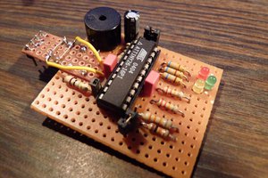
 Klaus Dormann
 Thomas Countz
 John Lonergan