Phil Wright
-
Register Control Board
03/01/2017 at 00:08 • 0 commentsJust because the register control board is green doesn't prevent us from testing it. The purpose of this board is to take information from the current instruction and use that to generate individual select lines for the 16 registers in our register file.
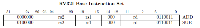
Many of the RISC-V instructions specify two registers as the source of values for the operation. These are called rs1 and rs2 in the ISA description. Here is the specification for the ADD and SUB instructions as an example.
![]()
Our board will take bits 15-18 (4 bits) and 20-23 (4 bits) as inputs. Notice that the instruction above specifies five bits allowing 32 registers to be selected from. But we are implementing the RV32E specification and not the full RV32I version. The RV32E spec only supports 16 registers, so we can simply ignore the most significant bit as the top 16 registers will never be referenced.
We assume that the code running on our CPU is valid, a commercial system would have checking for invalid instructions and accessing registers out of range. We are not going to bother with that, if your code is wrong then good luck with strange actions occurring!
So, bits 15-18 arrive at the board representing the rs1 field and are decoded into 16 output lines with only the matching register line selected. In practice, we have implemented the register storage boards to output on a low value. So 15 lines will be high and the matched register number will be set to low.
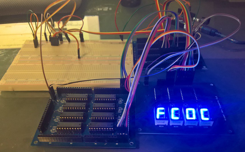
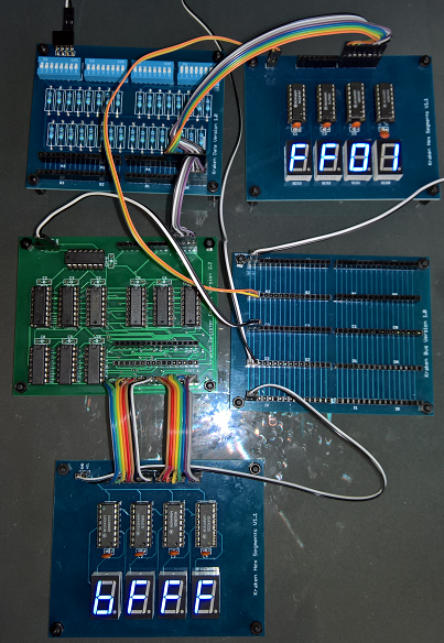
We can see this being tested and working below...
![]()
The top left shows our fixed value input board. It has a value of 01 as shown by the output on the top right hex display board. The green board outputs 16 lines and the hex value of that can just about be seen as BFFF or 1011111111111111 as binary. Starting counting at zero it has indeed selected the first line if you start count from the left-hand side. I have tested it with all 16 input values and it does indeed select the correct bit appropriately.
You might be surprised that it counts from the left and not the right side. Well me too and it turns out I make a snafu on the design. When I reorder it in blue I will rotate the output headers 180 degrees so it matches my expectations. It is not a big deal but as I want to reorder in blue anyway I might as well make the change. It will make wiring slightly neater.
Bits 20-23 from the instruction provide the rs2 field and are decoded in exactly the same way and simply output on a different header. The final functionality is similar but a little more complicated. Many instructions use the rd field to specify a destination register that should be written to with the result of the operation.
So we need to decode from a binary number to 16 values. But this time we also need to invert the outputs because writing to a register really does need to be high for a write and low for ignore. Simple enough we just add a bunch of NOT gates. But we also need to ensure we only write when the CLK occurs and the WRITE line is defined. Only some instructions need to update a register and this decoding will set the WRITE line. We only want the update to occur synchronously on the next CLK signal. So, we AND the CLK and WRITE and only when both are set do we enable the outputs for write lines.
This sounds fine in theory. Time will tell!
-
Am I going colour blind?
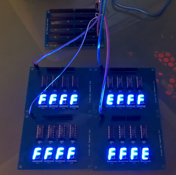
02/28/2017 at 22:45 • 2 commentsThe next batch of PCB's are in...
![]()
Hang on. I always order blue boards for my cool looking blue CPU. What the hell is this? I double checked my online orders and sure enough, I selected blue for them all. After 8 orders with PCBWAY.COM this is the first mistake they have made. I wonder if they ran out of blue board and just substituted? Wouldn't surprise me.
-
Never trust your Eagle
02/20/2017 at 08:51 • 6 commentsI recently took delivery of some more PCB's from PCBWAY. Given I have never managed to get a design to work the first time around I was not optimistic. Sure enough, I had made a mistake that messed up the board.
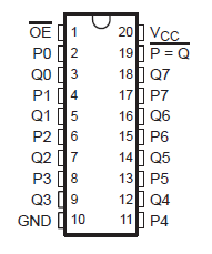
Using Eagle the 74688 IC has an P = Q output pin at the top right.
![]()
The 74688 is used to compare two 8 bit values. So naturally I assumed the P = Q output was HIGH when the two values are equal. When debugging the board I noticed it was the opposite value of what I was expecting. So time to check the actual datasheet.
![]()
What the! The schematic is inverted to the datasheet and so no wonder it doesn't work. So, it seems in future I need to double check the schematic against the actual datasheet for all IC's.
-
Calling clock experts...
01/27/2017 at 11:59 • 6 commentsI am designing a video driver for my upcoming computer. So I have a MX045HS which outputs a 25.175 MHZ signal which is needed to generate a 600x480 resolution VGA output signal. Connecting the crystal output to my trusty oscilloscope gives a pretty poor click signal...
![]() Using the reference source on the oscilloscope I can see that the poor signal is not a measurement/probe problem...
Using the reference source on the oscilloscope I can see that the poor signal is not a measurement/probe problem...![]()
I assume it is normal for a crystal to have such a poor signal. What is the standard way to improve this to a nice square wave? A standard circuit you can point me to?
-
Fixed value board
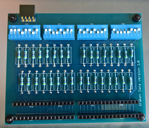
01/08/2017 at 12:10 • 9 commentsWell the latest batch of PCB's have arrived. Finally I have a simple 32 bit fixed value board. This allows me to set a 32 bit value using dip switches so I can then feed that value into other boards as test values. This makes debugging so much easier.
![]()
I must have picked the wrong component in Eagle to represent a standard resistor because you can see that the space allocated for each one is much greater then really needed. Fortunately it does not really matter as there is plenty of room on the board anyway. Although, adding 32 pull up resistors seems like I am doing things the hard way. There must be a simpler way of achieving the same effect? Any ideas?
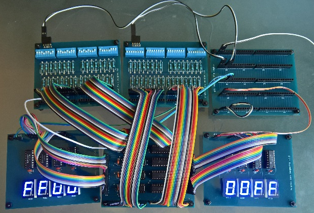
I used the boards straight away to test each of the 2-1 mux boards I have built. I can set two values going in and then use two display boards (each display board only shows 16 bits) to show the 32 bit output. Then just toggle the output select line and instantly check it works as expected.
![]()
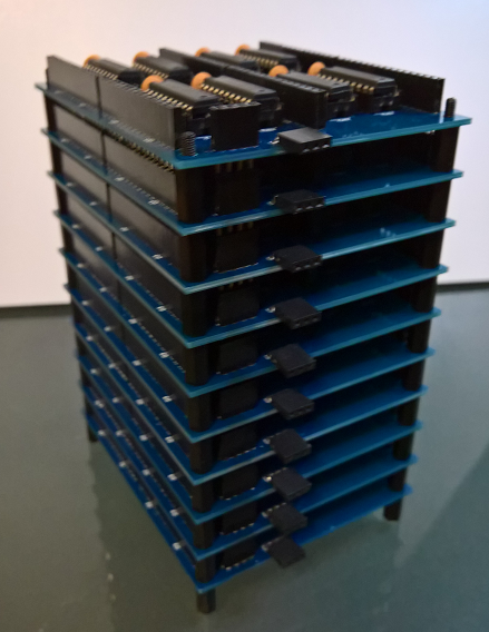
Next up was checking that each of the register store boards works. I need a total of 16 for the 16 general registers in the RISC-V ISA. Unfortunately I ran out of components once I have built 10 of them but it still makes quite the impressive vertical stack. The input and two output ports are all connected vertically Arduino style as is the power supply connector. That just leaves a 3 pin right angle connector for each register that allows for per-register selection for output and writing.
![]()
My next job is to get the components ordered to finish the stack and then the board that will be needed to generate the 16 sets of control outputs for them. Then finally the first major block of the CPU will be completed, the general register file.
-
Register Store
12/26/2016 at 10:10 • 1 commentI finally got some free time over Xmas to test out the register store board. It needs to store 32 bits so I use 4 x 74HC574 in order to store the value for output on port A and then another 4 to store the same value output on port B. So the value is stored twice but always updated together on the write line going high. Because the '574 has buffer out lines it means we end up not needing any separate buffer drivers. Remember that there will be 16 registers all connected to the port A and B and so we can only output when the specific register is selected.
![]() The left board is the register store and the right just a simple bus board used to distribute values and power. Now I need to order some for '574 chips so I can build out the other 14 that I need.
The left board is the register store and the right just a simple bus board used to distribute values and power. Now I need to order some for '574 chips so I can build out the other 14 that I need. -
Fame at last
12/20/2016 at 04:34 • 3 commentsI was browsing the popular Hacker News website yesterday when I noticed something a little unexpected. Someone had submitted a link to this project!
![]()
It stayed at the top spot for several hours and resulted in the project views jumping from about 1K to 6.5K overnight. Guess I had better pick up the pace and make more progress!I will be designing some new PCB boards in the evenings this week with a view to ordering them from PCBWay before the weekend. I have the following two weeks off as holiday so they should arrive during that time allowing me to continue with development.
-
Mux
12/18/2016 at 06:35 • 0 commentsMy CPU design calls for several multiplexers that allow the output to be selected from 2 different input values. For example, one of the inputs to the ALU is chosen from either the program counter or output port A of the register file. The design for this is pretty trivial.
I use 8 x 74HC241 to perform the actual switching of 2 x 4 input bits to 4 output bits. With the constrained PCB size of 100m x 80m we have enough room for the first 32 bit input at the top and the second input at the bottom of the board. With the IC's in the middle we have the bottom 16 bits output on the right edge and the top 16 bits on the left. So the PCB is very busy with headers around all the edges and filled with IC's.
You can see the mux board at the bottom left of the image...
![]()
I am only testing with 4 bits in the image. So the first input is 0xC, the second input 0x0 and because the selection bit is high the output is 0xC. Now I just need to order enough headers and IC's to make another 5 or 6 and I should have the mux requirements covered. -
Debug boards
12/16/2016 at 11:23 • 3 commentsDebugging designs is going to be much easier with a way to see the values being passed around. Using LED's is all well and good but does not scale well to 32 bit buses, especially if you need to look at three such buses at the same time. I would have preferred the debug board be able to show a 32 bit value but it is not possible to fit the 8 segment drivers as well as 8 segment displays on a single board. Instead we will have to settle for half of that.
So time to create a debug board that is able to display the value of a 16 bit input using 7 segment displays as the output. As each 7 segment display needs to shows values from 0 to F that means we need a driver that takes in 4 bits and outputs the appropriate 7 segment output lines. Looking around it is easy to find drivers for decimal (BCD) but they do not show the values from 10 to 15 as the needed hex characters. Instead they all show characters such as h, e, l and p so that you can spell out the word 'help'. The only driver I could find that I could also buy online is the MC14495 from Motorola. They have not been made for quite some time but someone in China has a warehouse full of them because I was able to get 20 of them from AliExpress. Their production dates range from 1987 to 1997.
By applying power but letting the data lines float I get the following example output...
![]()
At the top you can see the other board I have created, a simple bus board that has two lanes of 16 bits and will be used to distribute values to various boards in the finished CPU. In this case I am using the first two bits to distribute power and ground to the debug boards.Yes, these two boards and pretty trivial but when you have never designed any electronics before it is good to start simple and work your way upwards. Small steps!
-
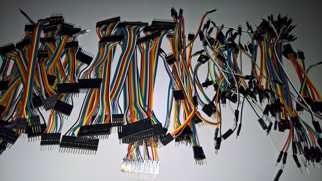
DuPont Connectors Galore
12/16/2016 at 11:04 • 3 commentsOne disadvantage of a 32 bit CPU is that your internal and external connections are 32 bits wide. That makes for a lot of wires. So time to start making plenty of cables for working with prototype boards and hooking everything up. Rather than buy them ready made, which is surprisingly expensive, I have decided to make them myself. So some ribbon cable, DuPont headers, connectors and a crimper...
![]()
World's first 32bit Homebrew CPU
Creating the world's first 32bit homebrew CPU using 74' series logic.


 Using the reference source on the oscilloscope I can see that the poor signal is not a measurement/probe problem...
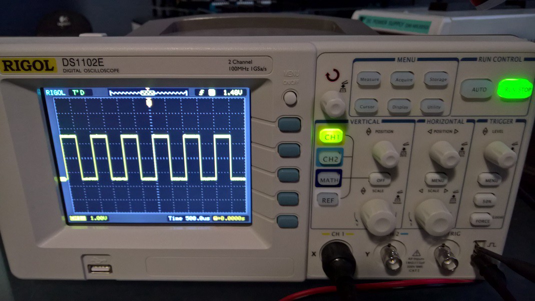
 The left board is the register store and the right just a simple bus board used to distribute values and power. Now I need to order some for '574 chips so I can build out the other 14 that I need.