Close
0%
0%

MultiMPPT

A low cost and high efficiency Maximum Power Point Tracking (MPPT) charge controller with multiple inputs for solar panel setups.

Public Chat
Similar projects worth following
MultiMPPT is a Maximum Power Point Tracking (MPPT) charge controller with multiple inputs. This project aims to provide a low cost and high efficiency solution for a charge controller (MPPT) for photovoltaic (PV) systems.

Lowering the prices of charge controllers creates an incentive for the adoption of clean energy solutions, in this case the use of solar panels. In the same way, increasing the efficiency of such systems will create an additional incentive for the installation of clean energy solutions, which stand out when compared to other sources of energy that are less efficient. All of these incentives will help to accelerate the adoption of photovoltaic systems, because they will not only be a source of clean energy but also will solve the needs of the customers.

This project was submitted for the Hackaday Prize 2022 Sustainability, Resiliency, Circularity, aiming to solve the challenge of Planet-Friendly Power.

Why is MultiMPPT a solution? yet another MPPT to be added to the list?

The MPPT is designed to be competitive with the current market of charge controllers. Therefore, the targeted voltage input would be 48V or higher, a voltage output of 12V or 24V and a 10A or higher current.

But this device will differentiate itself from other alternatives by having multiple MPPT inputs that will increase the efficiency under shading conditions, a feature that can be seen on a few expensive MPPT solutions found in the market. A budget priced MPPT with multiple inputs has the potential to create a great impact in the market of charge controllers and push it to achieve lower costs and higher efficiency.

Components of the Solar Panel System

A charge controller is used to limit the electric current that goes IN and OUT of a battery. In photovoltaic systems, the charge controller is connected to the solar panels (input), the battery pack and the load (output). A common load used in these systems is an inverter, a device that converts constant current (DC) to alternating current (AC). In this context, an MPPT is a charge controller that uses the technique named maximum power point tracking, a technique used to maximize the energy extracted from a source (in this case the PV modules).

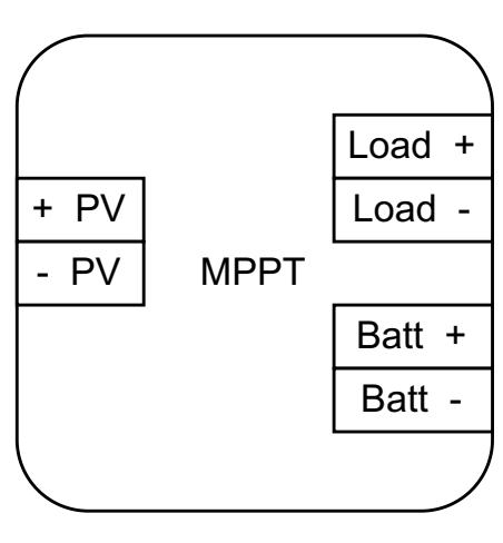
How to connect MultiMPPT to the other components in the Solar Panel Setup

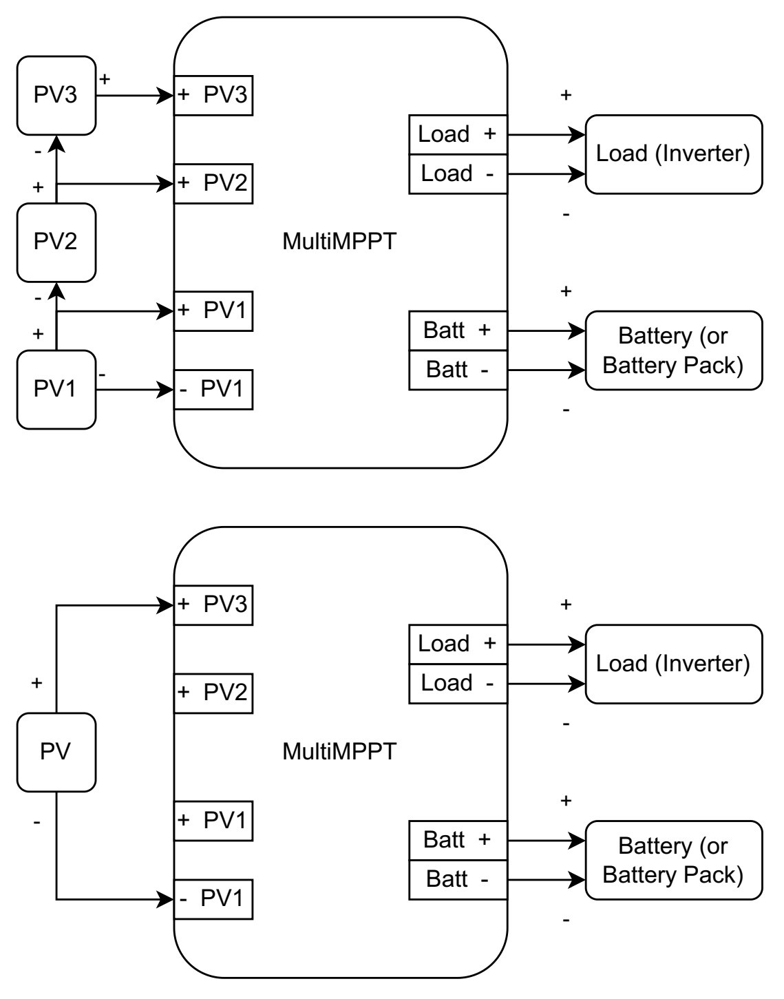
The following image presents how the proposed MPPT is used. In the image a group of solar panels (PV) modules connected in series is used as the source of energy, but a single PV can be used. The MPPT is also connected to the battery (or battery pack) and the load (e.g. an inverter).   

Proof of Concept - Simulation 

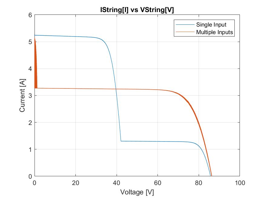
The benefit of the architecture that will be used in the design is that provides a higher efficiency under shading conditions. To create a proof of concept a simulation was designed where the input source are two solar panels serially connected (PV string), and one of them receives an irradiance considerably lower than the other one (i.e. shading). The following graph shows the results, where the blue line represents the power curve of the system when the PV string is connected in the conventional way (only + and - inputs for the PV), and the orange line represents the power curve when extra MPPT inputs are being used.

For more information about the proof of concept check the following log, or the repository that contains all the files used in the simulation.

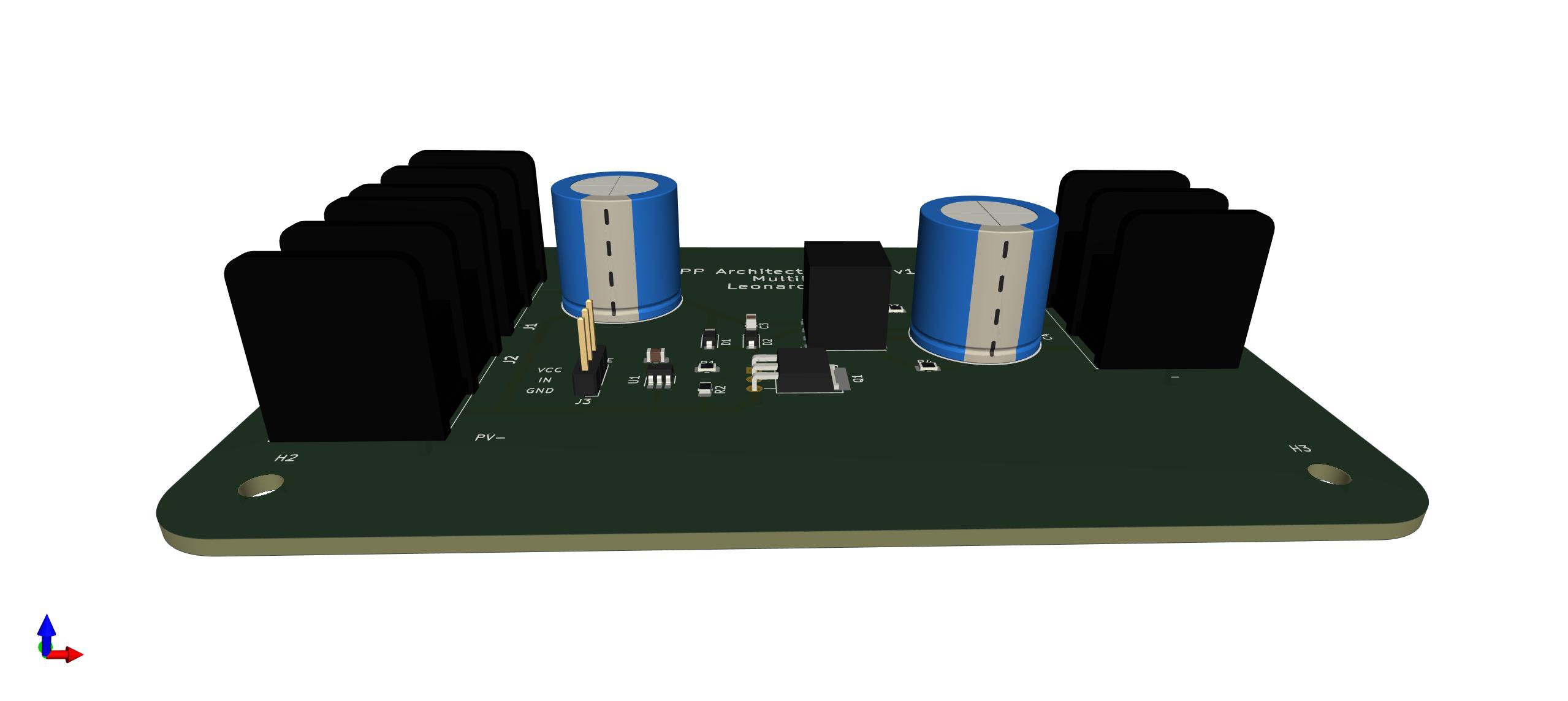
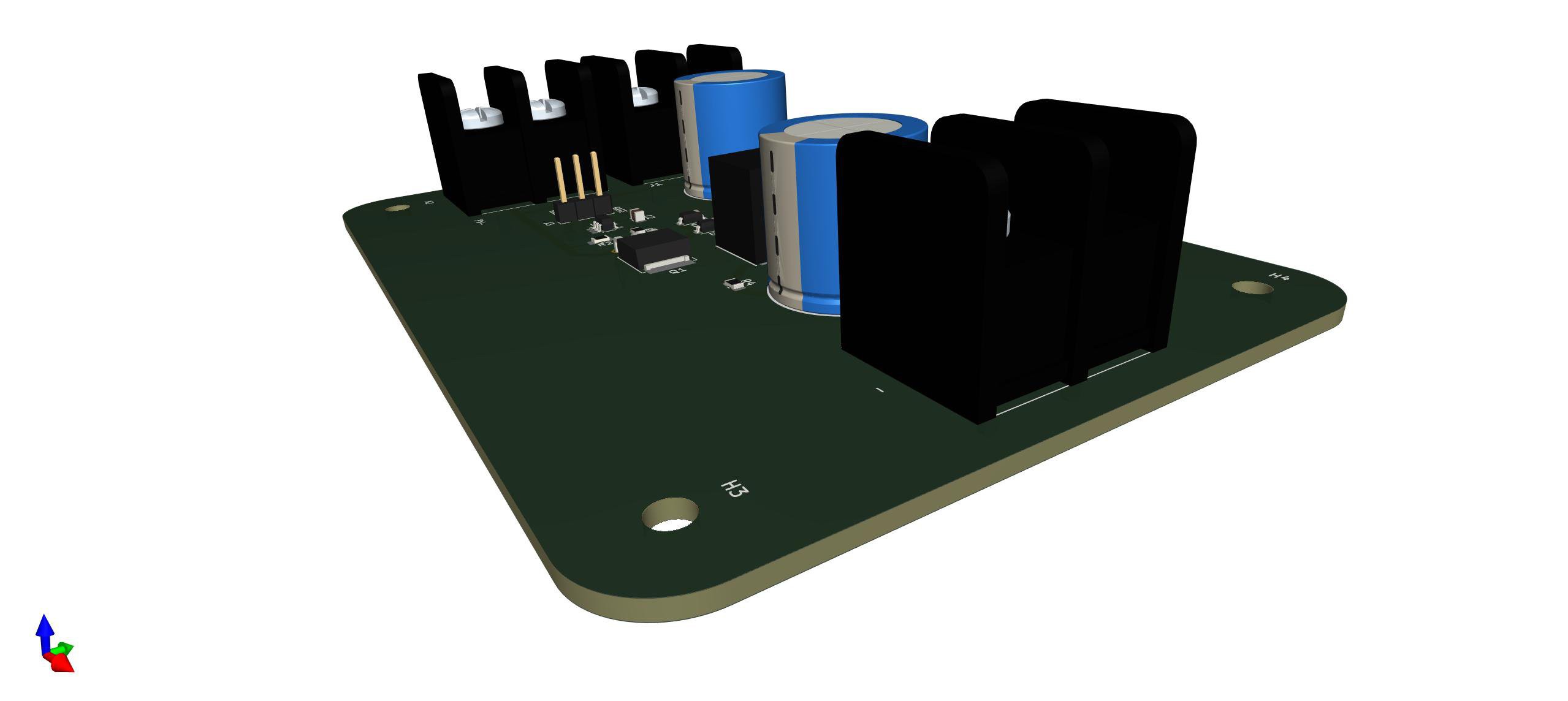
Proof of Concept - PCB Design

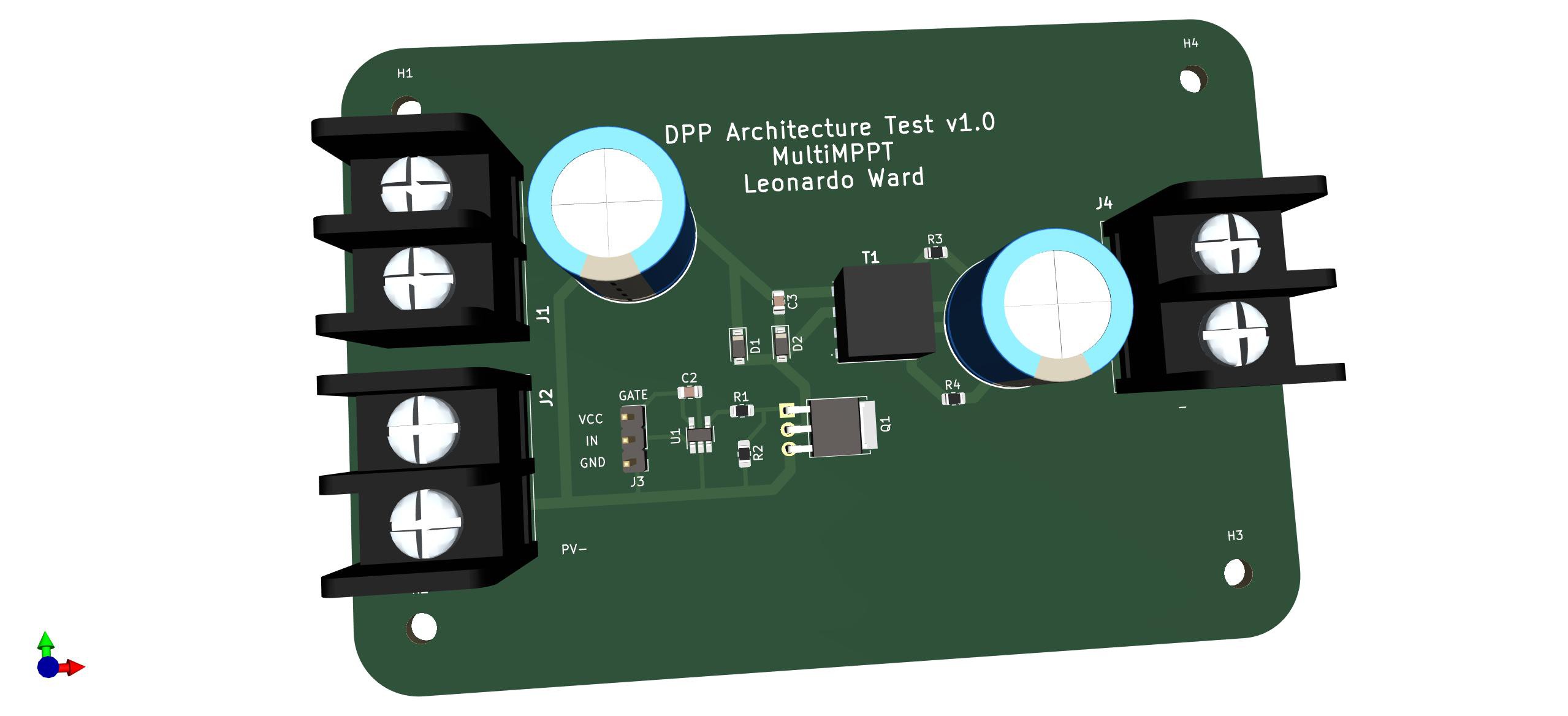
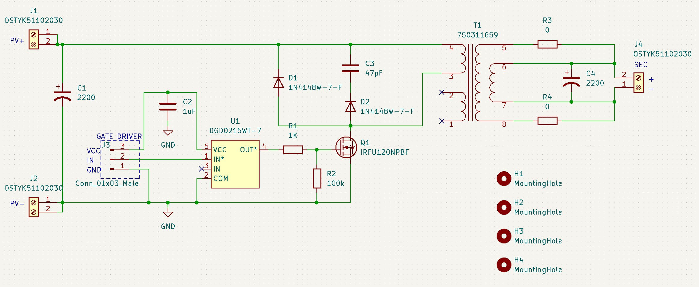
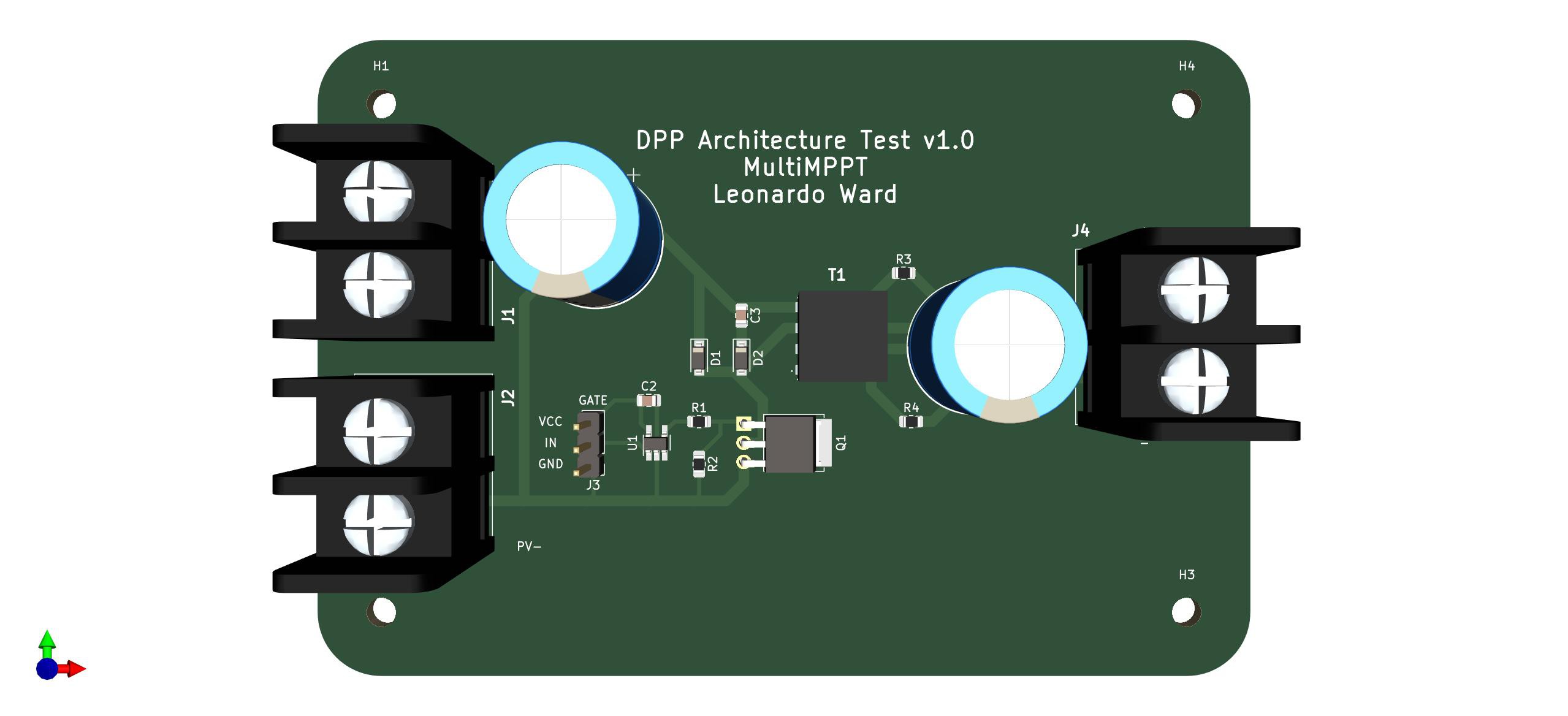
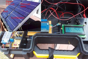
Once the DPP architecture is tested in simulation, the following PCB was design to perform real world tests of the DPP architecture, which is the most important element of the MPPT, it allows the connection of multiple inputs and the overall performance and maximum power point of the solar panels.

Even though the DPP architecture is not the complete circuit of the MPPT, it is important to mention that the goal is to finish the complete MPPT with connections for the PV circuit, the load and the battery (or battery pack). Since this is one of the most important parts of the design, it was simulated first, and I am focused on performing tests with the DPP Architecture PCB to verify the efficiency of the solar panel setup.

For more information about the PCB design check the following log, or the repository.

The following image shows how to connect a serially connected solar panels (with additional bypass diodes) to 2 DPP Architecture PCBs, and the expected output of the circuit. 

For more information about the connections check the instructions on How to connect the DPP Architecture PCB to the Solar Setup, more information about this topic will be added in the future.

Next Steps

  • Finish the design of DPP Architecture Test PCB
  • Design support circuits to measure voltage and current on the MPPT
  • Prepare a test bench for the DPP Architecture with solar panels
  • Solder and test the DPP Architecture Test PCB
  • Design the full MPPT PCB: including...
Read more »

LICENSE

GNU General Public License v3.0

license - 34.33 kB - 05/01/2022 at 11:22

Download

DPP-Architecture-PCB.step

3D Model (STEP) of the DPP Architecture PCB

step - 899.30 kB - 04/30/2022 at 21:16

Download

  • 2 × 228CKS050MQW Capacitors / Aluminum Electrolytic
  • 1 × CL21B105KAFNNNE Capacitors / Ceramic
  • 1 × 08051A470JAT2A Capacitors / Ceramic
  • 2 × 1N4148W-7-F Discrete Semiconductors / Diodes and Rectifiers
  • 3 × OSTYK51102030 Electronic Components / Misc. Electronic Components

View all 11 components

  • What does it mean to be a low cost solution?

    Leonardo Ward05/01/2022 at 12:17 0 comments

    At the current stage of the project, it is a little early to state that the solution being developed is low cost, and while the MPPT is designed with the idea of achieving a low price in mind it is a good idea to take a moment to consider how we can define a low cost solution in this context. 

    We can analyze the cost from two different perspectives: 

    • The cost of the device compared to other MPPT alternatives. 
    • The cost of the overall system and how the technology being used in the MPPT can impact the price of other components in the solar panel setup.

    To consider if the proposed device is an affordable solution we have to review the state of the market, and compare to other equivalent alternatives. As  reference we can look at the articles: “Best MPPT Solar Charge Controllers 2022” from Clean Energy Reviews and “Best MPPT Solar Charge Controllers: 12 Best MPPT Solar Charge Controllers for Off-Grid Power” from Off the Grid Power Boom. In both articles there are different MPPT models from different manufacturers that have different current outputs (20A, 30A, 40A up to 60A) and different voltage inputs (12V, 24V, 48V and higher), from those models we can observe a price range from 87$ to 499$, where the 12V/24V 20A models tend to be the cheaper alternatives in the 87$ to 149$. At this stage of the project we can have 100$ as a maximum price that could be considered for an affordable MPPT with typical power inputs 12V/24V and lower power outputs.

    The price of the complete system is affected by the compatible input and output voltages of the MPPT. For example: considering an MPPT that has a power output of 120W, if the voltage output is 12V then the output current is 10A, but if the output voltage is 24V then the output current is 5A. The amount of current affects the specifications (and price) of the components connected to the output of the MPPT, like cables, which are more expensive the higher the current they can manage. 

    The same analysis can is valid for the input of the MPPT, that is the voltage generated by the PV, the higher the voltage the PV the less current it provides for the same power, the article “48V Volt Systems: The future of Off-Grid Solar” by Renogy compares 12V to 24V systems and highlights the benefits of higher voltages, which are: they are safer (because they have less current running through them), use less expensive batteries and wiring, they tend to have a higher efficiency and are scalable. But the price of the solar panel does tend to increase with the higher voltage, the article “How to Choose Between a 12V and 24V Solar Panel?” by Loom Solar evaluates the differences between PV systems with 12V and 24, and mentions how 24V solar panels tend to be more expensive and have a higher price. Similar to batteries, solar panels can also be connected in series to have a higher voltage, which gives more flexibility when considering the overall price.

    In conclusion, a new MPPT alternative can minimize the costs of the PV system by having higher voltage inputs and higher voltage outputs, reducing the value of the current at the same power output. And the device can also reduce the price of the system by being less expensive than other alternatives while providing similar (or better) performance and functionalities,  to achieve this point, the device should be under the $100 price.

    References:

    48 Volt Systems: The Future of Off-Grid Solar . (2022). Retrieved 1 May 2022, from https://www.renogy.com/blog/48-volt-systems-the-future-of-offgrid-solar-/

    Best MPPT Solar Charge Controllers: 12 Best-Seller MPPT Controllers. (2022). Retrieved 1 May 2022, from https://offgridpowerboom.com/mppt-solar-charge-controllers/

    Best MPPT Solar Charge Controllers 2022 — Clean Energy Reviews. (2022). Retrieved 1 May 2022, from https://www.cleanenergyreviews.info/blog/best-solar-charge-controllers

    How to Choose Between a 12V and...

    Read more »

  • DPP Architecture Test - PCB Design and Bill of Materials

    Leonardo Ward04/30/2022 at 20:31 0 comments

    This PCB was designed to test the DPP architecture used in MPPT designs. The software used to designed the PCB is Kicad 6.

    To get the PCB design (e.g. schematic, PCB, gerber files) check the following repository.

    The tests performed with this PCB will contribute to develop the project MultiMPPT, that is a low cost high efficiency MPPT with multiple inputs. 

    Hardware Design

    The following image contains the schematic of the PCB:

    Where:

    • J1, J2 and J3 are used to connect the solar panel and connect to other components inside the MPPT (during the tests).
    • T1, C1, C4, Q1, R1 and R2 are the main components of the Flyback Converter.
    • D1, D2 and C3 create a snubber circuit to protect Q1. There will be used D2 + C3 or D1.
    • U1 and C2 is a gate driver to facilitate the change of state of Q1 at high frequencies (controlled using a microncontroller connected to the board).
    • J3 is a connector to give access to the gate driver.

    PCB

    Bill Of Materials

    NameQuantityPrice per unit (USD)
    PCB1$1.8
    2200µF 50V Aluminum Electrolytic Capacitors Radial2$1.65
    1µF ±10% 25V Ceramic Capacitor X7R 08051$0.10
    47pF ±5% 100V Ceramic Capacitor C0G, NP0 08051$0.14
    Diode Standard 100V 300mA (DC) SOD-123 1N4148W2$0.18
    2 Circuit 0.374" (9.50mm) Barrier Block Connector Screws with Captive Plate3$1.05
    N-Channel 100 V 9.4A (Tc) 48W (Tc) Through Hole IPAK (TO-251AA) IRFU120NPBF1$1.06
    1 kOhms ±1% 0.125W, 1/8W Chip Resistor 08051$0.10
    100 kOhms ±1% 0.125W, 1/8W Chip Resistor 08051$0.10
    0 Ohms Jumper 0.125W, 1/8W Chip Resistor 08052$0.10
    Flyback Converters For For DC/DC Converters SMPS Transformer 1500Vrms Isolation 180kHz Surface Mount1$3.97
    Low-Side Gate Driver IC Inverting, Non-Inverting TSOT-25 (Type TH)1$0.80

    The overall price is $15.08 (USD), without taking into account shipping costs. This designed could be a cheaper, some components have higher specifications than those that are needed (e.g. power dissipation and current). 

    Keep in mind that the DPP architecture is not the complete MPPT, but is the most important element in the design (in my opinion) because it allows me to test the efficiency of the system under different conditions, and the use of multiple inputs.

  • Proof of concept (simulation) - Validating the claims of higher efficiency

    Leonardo Ward04/27/2022 at 20:23 0 comments

    Before working on the circuit design of the MPPT it is a good idea to simulate the PV system and create a preliminary proof of concept. The software used to simulate the system is Matlab Simulink. All the related scripts can be found in the following repository.

    The objective of the simulation is to test the DPP architecture used in the MPPT (Chu 2017) and verify that it works correctly. With the simulations we can visualize the benefits of using an architecture with multiple inputs vs a single input under different circumstances.

    The typical interface for a charge controller has 6 terminals: 2 for the PV, 2 for the load and 2 for the Battery. Of course, more elements can be connected to those terminals (e.g. an inverter). 

    The terminals dedicated to the PV can be connected to a single one or an array. The PV array (also called string) can be composed of cells connected in serial or parallel, and there are different benefits for those connections, for more information check the article “How to wire solar panels in series vs. parallel” from SolarReviews.  

    The proposed device allows for the connection of a single PV or a PV string, and includes multiple inputs for the different cells. In our case, the PV string is composed of serially connected cells.

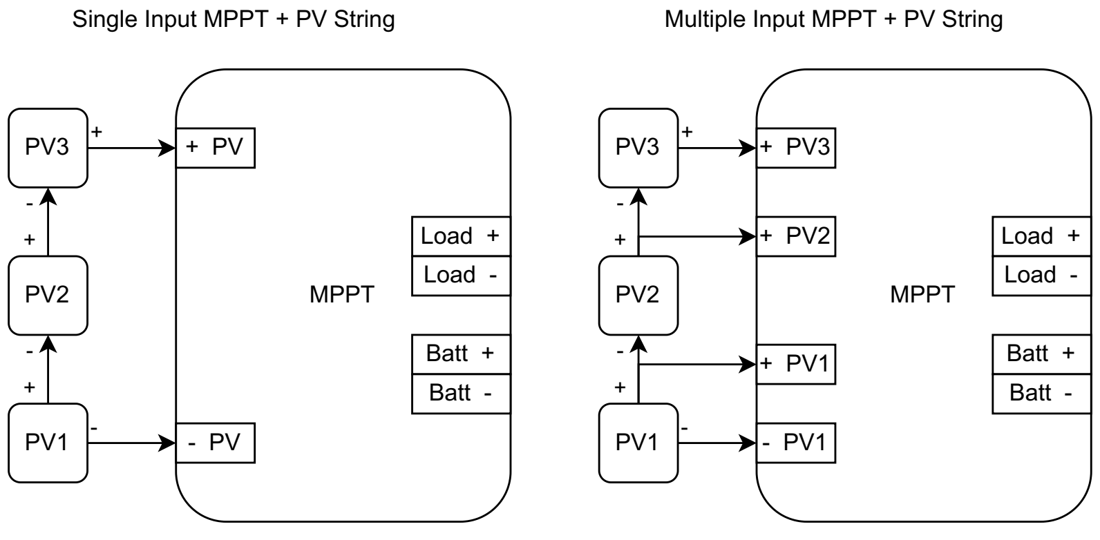
    The following image presents the Simulink Model used to simulate the system (the complete matlab/Simulink can be found in the following repository). The solar panel used in the simulation is the 175 Watt Monocrystalline Renogy RNG-175D-US.

    Multiple Input configuration for the MPPT

    The simulation contains 2 PV modules connected in series, and the design of the MPPT contains multiple inputs, so we can connect the positive terminals of the PV modules 1 and 2. But we can also disconnect +PV1 and use the typical connections +PV and -PV present in the single input MPPTs, which are being used widely in the market.  

    Single Input configuration for the MPPT

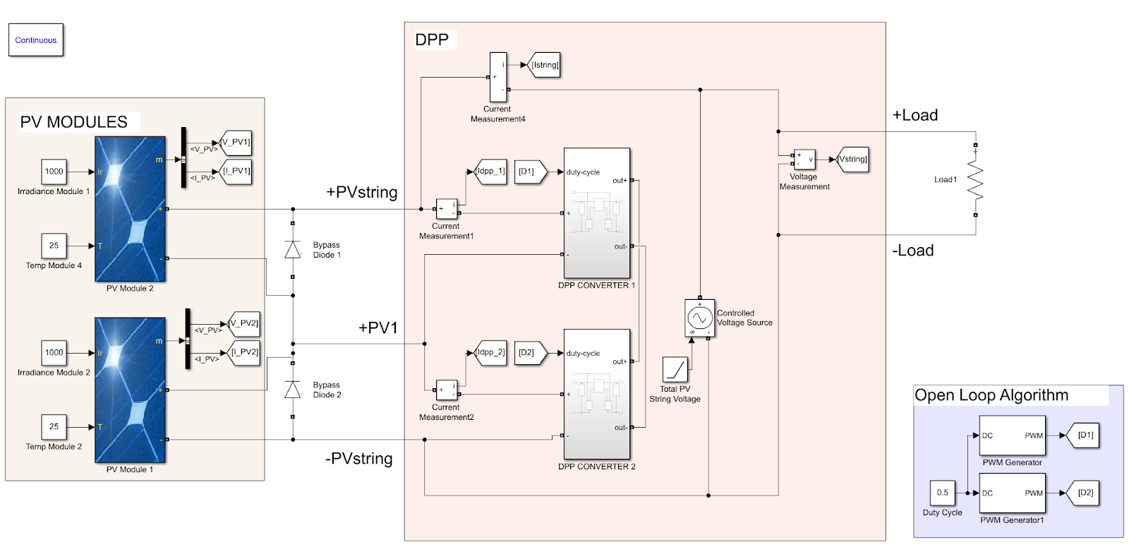
    Test 1 - Without shading
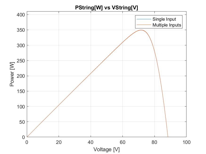
    In the first test both PV modules receive the same irradiance (1000 W/m2). The following images present the Power(W) vs Voltage(V) and Current(A) vs Voltage(V) curves.

    The graphs show that the MPPT is working correctly, also, it is possible to observe the same performance for the single input and multiple input configurations, or at least is close enough that more tests would be required to separate the results. 

    Test 2 - Shading on one of the PV modules

    In this test the PV module 2 receives an irradiance of 1000 W/m2 and modele 1 receives an irradiance of 250 W/m2 (shading). The following images present the Power(W) vs Voltage(V) and Current(A) vs Voltage(V) curves.

    In this test we can observe the benefits of having an architecture with multiple inputs for PV arrays. Looking at the power graph we can observe the two local maximum points, which suggests a performance that is not consistent where the MPPT is focused on a local maximum point. The results from the architecture using multiple inputs suggest a significantly better performance, which validates the hypothesis that the device has an improved performance compared to other charge controllers found on the market that only have single inputs when we consider cases with some amount of shading.

    Now, looking at the results it is possible to argue that it is a problem with this architecture, but the results are consistent with other results observed on similar architectures under shading conditions. Maghami (2016) discussed how the performance is affected by shading conditions, for more information about it check the research from Maghami (2016) or check the later post “Increasing the efficiency under shading” discussing design decisions and the benefits of multiple input MPPTs. 

    References:

    Chu, Guanying & Wen, Huiqing & Jiang, Lin & Hu, Yihua & li, Xingshuo. (2017). Bidirectional flyback based isolated-port submodule differential power processing optimizer for photovoltaic applications....

    Read more »

  • Market Size and Consumer Considerations

    Leonardo Ward04/27/2022 at 19:33 0 comments

    The market of the Solar Charge Controllers have been rapidly increasing every year, the website Fortune Business Insights created a detailed study about this topic, just as a reference, it reported that the market size of Solar Charge Controllers just in North America is 0.39 billion dollar. But the market of solar charge controllers is divided in two different technologies: pulse width modulation (PWM) and maximum power point tracking (MPPT).

    According to Fortune Business Insights “Currently, the MPPT charge controller segment accounts for a lesser share in the market than the PWM charge controller due to the difference in the price of the two. But, the operational advantages such as better efficiency in low sunlight, long wire ruins, and low battery charge would cater to the rising share of maximum PowerPoint tracking (MPPT) charge controller during the given forecast period.”

    Looking at the report, it is possible to conclude that innovations in the technologies of MPPTs can have a great impact in the market, which is massively conquered by PWM chargers due to price. A reduction in the cost of MPPT chargers can create a significant impact in a market that has the size of 0.39 billions just in North America, while also providing great benefits for the consumers because of the increased efficiency of the technology.

    Targeted Specifications for Better Adaptability

    Similar to any new development, it is always important to consider the point of view of the consumer. For that we will evaluate two types of consumers:

    • The consumer that is building a new PV system and is also interested in using the MPPT technology, will compare different alternatives and the proposed device can potentially stand out because of the increased efficiency provided by the extra MPPT inputs.
    • The consumer that already owns a PV system and is looking to replace the PWM or the MPPT controller will be interested in the increased efficiency but also will need the new technology to be as compatible as possible to the already implemented system.

    With those thoughts in mind, the proposed solution should be compatible with the most common specifications of batteries, solar panels and inverters. Looking at the best selling energy controllers in Amazon we can se typical specifications for an MPPT system, the list updates constantly so it might not be the best reference, we could also look at the article “Best MPPT Solar Charge Controllers: 12 Best MPPT Solar Charge Controllers for Off-Grid Power” from Off Grid Power Boom to obtain some references.

    After comparing with other alternatives the following target specifications are proposed for the design:

    • 48V or higher voltage input
    • 10A or higher output current
    • 12V/24V output voltage


    References:

    Amazon Best Sellers: Best Renewable Energy Controllers. (2022). Retrieved 27 April 2022, from https://www.amazon.com/Best-Sellers-Renewable-Energy-Controllers/zgbs/lawn-garden/2236627011

    Best MPPT Solar Charge Controllers: 12 Best-Seller MPPT Controllers. (2022). Retrieved 27 April 2022, from https://offgridpowerboom.com/mppt-solar-charge-controllers/

    Solar Charge Controller Market Size, 2. (2022). Solar Charge Controller Market Size, Share, Growth | Report, 2026. Retrieved 27 April 2022, from https://www.fortunebusinessinsights.com/solar-charge-controller-market-102158 

  • Increasing the efficiency under shading conditions

    Leonardo Ward04/27/2022 at 01:17 0 comments

    The proposed design has an increased efficiency under partial shading of PV modules, this is a benefit of the DPP architecture with an MPPT that has multiple inputs, one for each panel in the string (array of PVs connected in series). 

    The power output of the solar panels depends on the irradiance that reaches them therefore any obstruction that creates shading over the PV will decrease its efficiency. Maghami (2016) discussed how the electrical characteristics are affected by the shading produced by soiling. Divided the shading in two categories: soft shading such as air pollution and hard shading which occurs when a solid such as accumulated dust blocks the sunlight.     

    The following images present different common cases of shading that affect the solar panel setups.

    Shading caused by the dust accumulated on top of the solar panels.

    Shading caused by other buildings.

    Shading caused by a tree.

    According to Maghami (2016), "The result shows that soft shading affects the current provided by the PV module, but the voltage remains the same. In hard shading, the performance of the PV module depends on whether some cells are shaded or all cells of the PV module are shaded. If some cells are shaded, then as long as the unshaded cells receive solar irradiance, there will be some output although there will be a decrease in the voltage output of the PV module." (p. 1307).

    When considering a string of PV modules Maghami (2016) found that “the effect of soft shading of soil on a single string array is the same as the PV module discussed earlier.”  (p. 1314),  “when there is uneven hard dust on different strings in parallel, a voltage mismatch occurs. In this condition, which is called partial shading, different parallel strings, which are connected to a common inverter, deliver different voltages to the inverter. This makes it difficult for the inverter to seek the optimum point of voltage at which the maximum power is delivered.” (p. 1314).

    Since it is harder for the MPPT to find the optimum point of voltage under partial shading conditions, their efficiency decreases. As a solution to that problem, MPPTs with multiple inputs for the different PV modules in the string are recommended. They can achieve a higher efficiency under any scenario including sub-optimal conditions (soft and hard shading). 

    References:

    Maghami, Mohammad Reza & Hizam, Hashim & Gomes, Chandima & Mohd Radzi, Mohd Amran & Rezadad, Sina & Hajighorbani, Shahrooz. (2016). Power Loss Due to Soiling on Solar Panel: A review. Renewable & Sustainable Energy Reviews. 59. 1307-1316. 10.1016/j.rser.2016.01.044.  

View all 5 project logs

  • 1
    How to connect the DPP Architecture PCB to the Solar Setup

    The following image shows a typical photovoltaic (PV) string composed of serially connected solar panels (with additional bypass diodes) connected to two DPP Architecture PCBs.  

    While it is possible to connect the PV string to a single DPP Architecture PCB, it is recommended to have as many PCBs as solar panels are in the string. In that configuration the architecture works optimally and it is possible to take full advantage of the multiple inputs of the boards.

    It is important to remember that the DPP architecture is part of the MPPT, but not the complete circuit, that is the reason why the image presented before doesn't include the battery or the load (eg. inverter). The image is used to showcase how to connect the inputs and outputs of the DPP architecture, the part of the design that ensures maximum efficiency from the solar panels.

    The PCBs require a square signal that will be provided by a microcontroller, more images will be included to show those connections.

    The PVs used in the image are small 2.5V 1.2A solar panels, but the PCB can be used with high wattage high voltage alternatives. More information about the maximum ratings of the PCB design will be added in the future. 

View all instructions

Enjoy this project?

Share

Discussions

Similar Projects

Does this project spark your interest?

Become a member to follow this project and never miss any updates