Tom Dowad
-
First Project Code Release
05/27/2022 at 19:47 • 0 commentsThis is missing the image, I'm creating a new one so I can provide that without copyright issues. But the image file is there so you can see the form. Or make your own. Get a 240x240 PNG @ 16 bits-per-pixel. Use your favourite language to convert the file into a C array. I haven't yet found the code I used for that...I'll share it when I find it or rewrite it.
I put the display driver in a separate file, because the .INO was getting a bit big, and so the display driver as a component could more easily be swapped.
The form of the MIDI receiver -> value -> display is in place. So its easy to follow the design pattern and create new views.
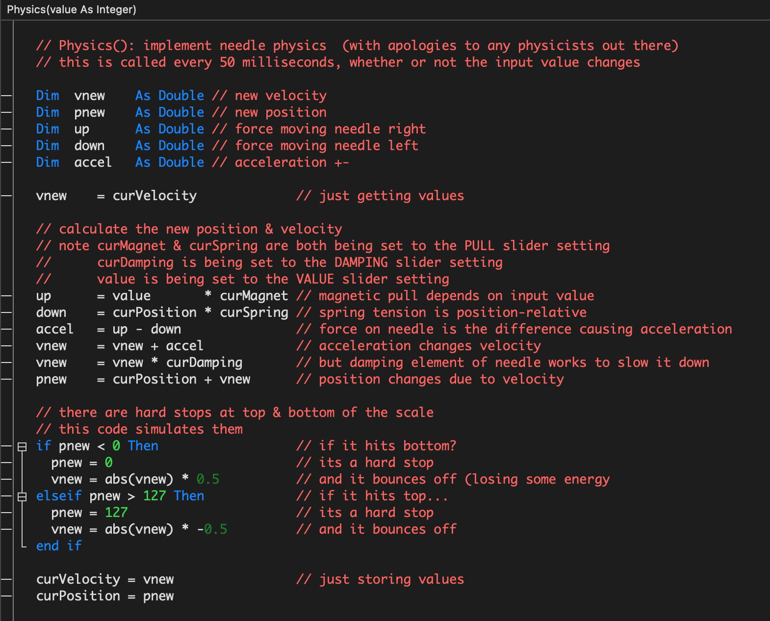
The needle physics has been moved over from the test code into the Arduino project. Because the sampling rate differed from the test code, the constants were different. The algorithm is, I believe, identical. The result of needle physics is that the needle will not instantaneously pop from one position to another without moving through the space between, and when it arrives at its destination, it tends to overshoot then bounce back. Also it will tend to bounce off the hard stops at each end.
Any questions, let me know. I will improve the commenting as needed.
-
Pitch Wheel Message Intepreter
05/19/2022 at 02:50 • 0 commentsThe meter box has so far been only a set of VUs, but my intention is to interpret a range of MIDI message types into different displays. A few days ago I got the pitch wheel message display working, though it has no PNG background image yet.
The pitch wheel message carries 14-bit value, that is interpreted as positive or negative. Typically the full scale positive and negative values will result in a pitch change up or down one octave.This is quite straightforward to convert into a display, using the same needle as with the VUs. A few parameters in the needle line drawing function needed to be changed to get the needle to move in a way appropriate to the task.
There was one surprise. I had just bought the keyboard controller through craigslist, and was not familiar with its operation. At first I was thrown by the MIDI activity, so I used my protocol analyser to have a look. It turned out this device uses MIDI's running status. With running status, the device sends the pitch wheel command once, then any number of the 14-bit values after that, as long as no other MIDI messages needing to share the cable. So running status was coded into the message interpreter.
-
Simulating Needle Physics
05/17/2022 at 20:35 • 0 commentsThere was some interest in the skeuomorph aspect of this project. That is, new tech simulating old. So I reckoned I might as well follow that thread. I got some new PNG images on order, inspired by vintage meters. And I reckoned I might as well get the needles moving in a way that is more realistic, ie simulating physics.
Maker [sjm4306] did it in this project:
https://hackaday.io/project/181004-digital-vu-meter-with-analog-physics
I had a look at the code for that project. While I'm sure its quite accurate, I couldn't get my head around the PI method used. But I did pick up something from this implementation: that physics only required a few lines of code.
I didn't really understand how one of these meters worked either. So I went to Youtube, what else? This video was helpful:
I knew about the spring and the magnet, but I was surprised to learn about the damper, and how it was implemented. I could see the hard stops on each end. I had certainly "pinned" one of these needles in my day, but never seen the inner mechanics of it.
I was just about to jump into writing C code, then realized it might not be as easy as imagined. I often write code in Xojo, a VB-like language, for testing algorithms. Its fast, inputting values is easy, and it has a good debugger. VB is, like most languages, similar to C. And it was only a half-dozen lines of code.
Here is the code I settled on:
![]()
It is not the definitive physics simulation, but I am happy enough with the results.
Here is the simulation running:
Sorry its just a screen capture and no voice over. I will do better...next time.
The PULL setting is meant to simulate the amount of force applied by the spring (to the left) and the magnet (to the right). As it is increased, the needle moves faster. If set to 0.0 the needle won’t move at all.
The DAMPING setting is meant to simulate the damper, which is a drag on the needle movement and slows it down. In the code its as a multiplier on the velocity. If set to 1.0, the needle will oscillate, forever apparently. If set to 0.0, the needle will not move.
The VALUE setting only changes on mouse button release, not when dragging the slider. You’ll see when it changes as there is a numeric field up top.
Toward the end of the video I move the slider to minimum and maximum positions. Look for the needle bouncing off of the hard stops on either end.
I’ll get this algorithm into the rack unit shortly.
-
Some Video
05/14/2022 at 05:18 • 0 commentsI just made a short phone video to show the meters in operation:
In order to get a MIDI data stream to demonstrate the workability of 8 meters running simultaneously over one MIDI DIN cable (31250 baud), I programmed another MCU to generate it. That MCU generated sine waves, with a range of 0-127, then as each wave value would change, it output the value in a Control Change message.
My math on this is that all 8 displays could be updated about every 8 milliseconds. Given that a video frame rate of 30 frames-per-second (33 ms/frame) is generally adequate for smooth animation, 32 channels could be transmitted on one MIDI 1.0 cable. That would saturate the MIDI stream.
Rack Mount MIDI Meters
Eight small colour screens display MIDI data, in a 1U rack format