 ASHUMHRPROJECTS
-
1Story
This is a very advantageous yet easy to make project.
We call it " Automatic Room Light Controller ".
Benefits:-
In this project, we will see the Automatic Room Lights using Arduino and IR Sensor, where the lights in the room will automatically turn ON and OFF by detecting the presence of a human. Such Automatic Room Lights can be implemented in your garages, staircases, bathrooms, etc. where we do not need continuous light but only when we are present. Also, with the help of an automatic room light control system, you need not worry about electricity as the lights get automatically off when there is no person.
Applications
I’ve already mentioned a few applications of the Automatic Room Lights concept. Some of them are:
- Garage Lights
- Bathroom Lights
- Hand Dryers
- Toilet Flushers
- Security Lights
By following this guide, you will be able to know and make your Automatic Room Light Controller. This project guide contains the files necessary to help you step by step produce your own Automatic Room Light Controller. Please follow the steps of the project to get a positive result.
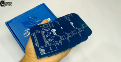
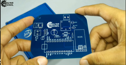
Step 1:- Get your PCB ready!
Talking about electronics
After making the circuit diagram I transformed it into a PCB design to produce it, to produce the PCB, I have chosen JCLPCB the best PCB supplier and the cheapest PCB provider to order my circuit. with the reliable platform, all I need to do is some simple clicks to upload the Gerber file and set some parameters like the PCB thickness color and quantity. I’ve paid just 2 Dollars to get my PCB after five days only, what I have noticed about JCLPCB this time is the "out-of-charge PCB color" which means you will pay only 2 USD for any PCB color you choose.
![]()
![]()
![]()
-
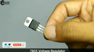
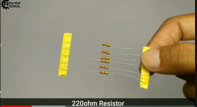
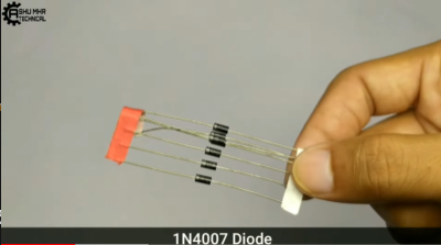
2Get all the Components Listed below images.
![]()
![]()
![]()
![]()
![]()
![]()
![]()
![]()
![]()
-
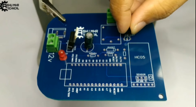
3Place all the components on PCB and solder it properly.
![]()
![]()
![]()
![]()
-
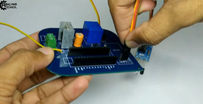
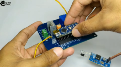
4Connect the IR sensor with the help of Jumper Wire.
![]()
-
5Then, Upload the code that will be provided below in Arduino Nano and connect it to the PCB.
![]()
![]()
-
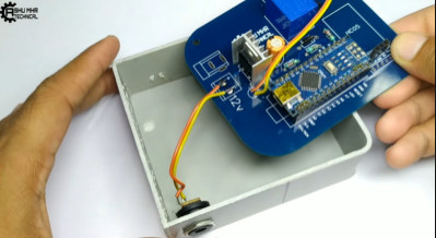
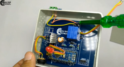
6Stick the PCB to the Custom designed PVC box and connect the 12 v power supply to the PCB for the input in the circuit.
![]()
![]()
![]()
-
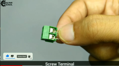
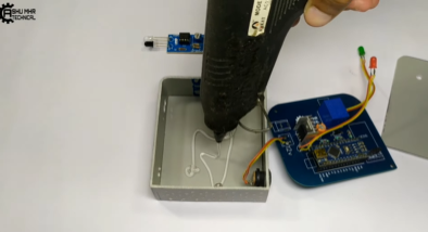
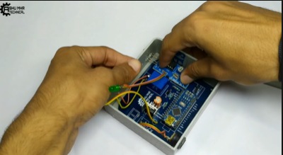
7Connect the Screw Terminal to the PCB for the relay output from the circuit.
![]()
![]()
-
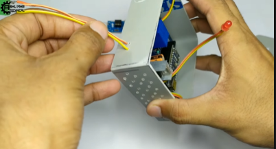
8Connect the IR sensor the circuit with the help of Jumper wire.
![]()
![]()
![]()
-
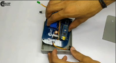
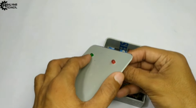
9Cover the Box and place all the components on their respective holes.
-
10Connect the appliances with the your Automatic Room Light Controller.
![]()
Automatic Room Light Controller
This is a very advantageous yet easy to make project.


Discussions
Become a Hackaday.io Member
Create an account to leave a comment. Already have an account? Log In.