 Mrinnovative
Basic-Motor-PWM-Speed-Control-With-555IC

This project is about, controlling a fan using 555IC with PWM. PWM is controlled with a potentiometer.
I drove a fan but you can use it for a DC motor. The circuit has a back-emf diode.
I did this project using a prototyping board but if you want to produce the PCB, I will share the Gerber files too.
Features
Input has a 500mA fuse for protection.
PWM is controlled with a 10k potentiometer
Min. duty-cycle limiting at %25
1.5kHz PWM frequency.
1A@12V input supply.
On/Off Switch.
Back-emf diode for the motor.
350mA max @ 12V fan.
I selected these features but you can change input power, minimum duty-cycle value, or frequency depending on your motor power. I will show you later.
Hi everyone! Today I came to you with a basic project. I made this project a simple and cheap solution for soldering fume filters. Whenever I try to solder, fumes always follow me and I don't want to breathe it anymore! And I want you guys to don't breathe those fumes too.
Circuit Material List
1xTLC555
1xIRF3710ZPBF
1x12V Fan
1x500mA fuse
1xOn/Off switch
1xDC Power Jack
4xSchottky or Standard Silicon Diodes
2x2.2uF, 1x1uF, 2x100nF, 1x10nF capacitors
1x10k Pot
1x3.3kOhm, 1x2kOhm, 1x1.2kOhm resistors
At least 5x5cm Prototyping board
Any adaptor plug above 500mA @12V
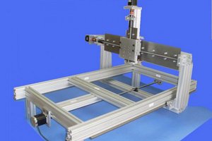
Mechanic Material List
If you want to make a box too, I will share the STL files.
Circuit protection box
Some support materials for holding the fan
2 sides tape
Some screws and nuts
As you can see in the photos above, a flexible, I guess aluminum material holds the fan. I found it in an old desk lamp.
Desingning the Schematic

How Does This Circuit Work?
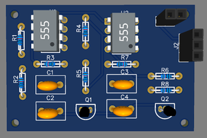
This circuit is working on the astable mode. In this way, we can simply adjust the C3 capacitor charging and discharging time with a 10k pot. D1 and D2 diodes block one side of the currents on the pot. R3 resistor is used for the limiting minimum duty-cycle value.
We need to have a minimum value because the fan can't work under the 3V. So for the 12V input, the %25 duty-cycle is equal to the 3V. The C4 capacitor is not necessary but you can use it for the line regulation. The D4 diode is for back-emf protection. In this way, you can use any DC motor.
The Q1 MOSFET is completely adequate. It can handle 100V and 49A!. If you want a more compact circuit, you can change it with another MOSFET that has fewer ampere value. So that, the size will be much fewer too. I used the F1 fuse because the circuit is plugged into the outlet.
If any problem with the adapter, the fuse popped up and protects the circuit.
PWM Frequency Calculation
1.5kHz works like charm. But under 20kHz can cause some audible noise. 1.5kHz has some audible noise too but it doesn't bother me. If you want to increase the frequency, you can choose any frequency under the table.
With the minimum %25 Duty cycle value;
2kHz → 50nF
3kHz → 35nF
5kHz → 20nF
10kHz → 10nF
15kHz → 7nF
20kHz → 5nF
By using TLC555 and IRF3710, you can increase the frequency 52kHz. But I am not suggesting it. Because discharging time getting too long according to the frequency. If you want to calculate your own frequency value, you can use this formula.
R3 = (Dmin * RPOT)/(1-Dmin) → Dmin: Minimum duty-cycle value. f = 1/(0,693*(R3+RPOT)*C)
MOSFET Gate Resistor Value Calculation
t first sight, it looks kinda difficult I know. But actually, it is just a simple capacitor theory. The capacitor is charged through the R1 resistor and discharged through the R1 + R2. If you add a diode parallel to the R1, it just discharged through the R2. TLC555 max. output current is 10mA. We have to choose the R1 value with respect to the 10mA.
R1 = Vo/Io → Vo is the out voltage of the 555IC and Io is the max. output current of the 555. 12V/10mA = 1.2kOhm
If we didn't use a diode parallel to the R1, the capacitor will discharge R1 + R2. The total resistance can be calculated like this.
R2 = (1-Dmax) / (-ln(Voff/Vout)Cgf) Dmax: Maximum duty-cycle...
Read more »
 sandy
sandy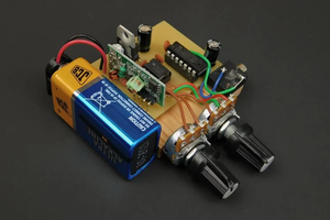
 Rhys
Rhys