Emilio P.G. Ficara
Emillotron - part 1
The title is a mix (a crasis) between Emilio (my name) and Mellotron. The Mellotron was used in the 1960s, in the time of the Beatles. In those years, long before “digital music”, someone invented a mechanical system that made a magnetic tape slide in front of a head when a key on the keyboard was pressed, thus reproducing the recorded sound. The device I am about to introduce to you has nothing to do with this… It is always about generating sounds and possibly music, but here we are going to use FM synthesis (this is Frequency Modulation, but it is not a private radio).
Many (MANY) years ago, I started my career as a firmware / software / electronic designer in a company that produced electronic musical instruments (keyboards, organs, etc.) and therefore had the opportunity to get in touch with everything new appeared on the market. When Yamaha came with FM synthesis (theorized by Chowning), suddenly a polyphonic and polytimbral keyboard could be created with a single chip! Of course, there was a lot of study to be made, but I love doing it and so, together with the music consultant, I “hacked” the registers of the chip to get decent and sometimes even indecent sounds, like alien calls!
Well, I found this prototype in my garage, almost empty. It was probably a test board, because there are a couple of flying wires underneath. Being about 40 years ago, I don't remember the details, but in all likelihood I had designed the card with the Rockwell 6502 micro (the legendary one) since at that time I was using an Apple II as a development system.
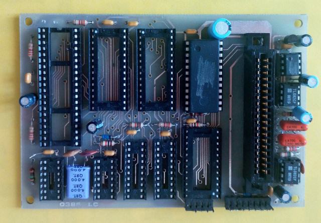
The only integrated chips left on the board are those related to sound generation, therefore the OPL-II chip, the DAC and two opamps with buffer and filter functions. Note that in those days there was no concept of sharing and everything was done not to be copied by the competitors! In fact, as you can see from the image, the names of the ICs are deleted and it is not an effect of the graphics program, but of a small cutter 🙂
Well, the device that I am about to present is part of a larger project which is an "integral relax machine". In short, this machine will be able to generate visual stimuli (strip of colored LEDs), acoustic (this sound generator) and tactile (boxes to be held in hand with motors that generate vibrations).
For the synthesis of FM sounds, I suggest you read an article of mine from a few years ago at this link: http://ficara.altervista.org/?p=1381 . The article had some success, also because I published the source files in C (converted from my originals in assembler) and everything was even mentioned by hackaday which is a beautiful site for innovative ideas and "hacks" of all kinds.
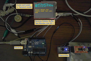
The project presented then was based on a 40 pin Microchip PIC driving a standard PC sound card (ISA bus, now obsolete stuff). In this new version, I decided to simply use a Yamaha OPL-II chip (YM3812) with an Esp8266 based circuit (mini D1 module) and suitable peripherals (I2C + SPI), developing the firmware (with appropriate conversions from the original) on Arduino platform. If only the OPL-IIs (two operators) are used the code is practically identical for both the chips used on the ISA sound cards and the YM3812.
Let's see what it takes to interface to the OPL-II chip. This is the pinout:
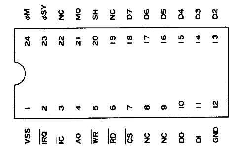
The signals necessary to write the various registers of the chip are: D7..D0 (the data bus); A0 the base address (note: there are many registers, but why is there only one addressing bit? Simple. If A0 = 0 is used, the address of the register to be read or write is sent to D7..D0; if A0 = 1 is used, the previously addressed register is written, so it is a two-step operation). Other control signals are / CS (chip select), / RD (read) and / WR (write). Finally we have / IC which is in effect the reset pin and / IRQ which is the interrupt output signal from the chip, which is not currently used.
The other pins are for the power...
Read more »
 Yann Guidon / YGDES
 Pero
Pero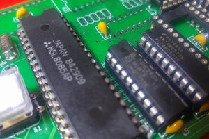
 Martin Maly