mircemk
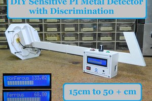
A metal detector is an instrument that detects the presence of metal nearby. This time I will show you how to make a very sensitive, but simple to build "Inductoion Balance" type of metal detector made with the help of Arduino microcontroller and several other components.
The Induction Balance principle uses two coils arranged in such a way that there is virtually no inductive pick-up between them. A modulated signal is fed in to one. When metal is brought near, the electromagnetic field is disturbed and the other coil picks-up an appreciably higher signal.
In a few of my previous videos you can see the making of different types of Metal Detectors. In terms of detection capability, this detector is the most sensitive, but also a big advantage is that it is a standalone instrument and does not use a smartphone, as one of the previous ones that has a sensitivity closest to this one. The construction is really simple thanks to the microcontroller, but also the module for weak signal amplification with LM358 IC which can be ordered for less than fifty cents. However for those who can not obtain this module, I also presented a schematic diagram in which the amplification is done with two standard NPN transistors, with the sensitivity of the device being the same as in the previous case.
The principle of operation is as follows: the Arduino generates a signal on pin 8, which is then amplified by a MOSFET transistor and fed to the Transmitter coil. Then, the signal of the Receiver coil is amplified with the LM358 module (or with two transistors in the second option) and carried to the A0 analog input. We also have two potentiometers on analog inputs that regulate the reaction threshold, and thus the sensitivity of the instrument. The buzzer and Led serve as a sound and visual indication when detecting a metal object.
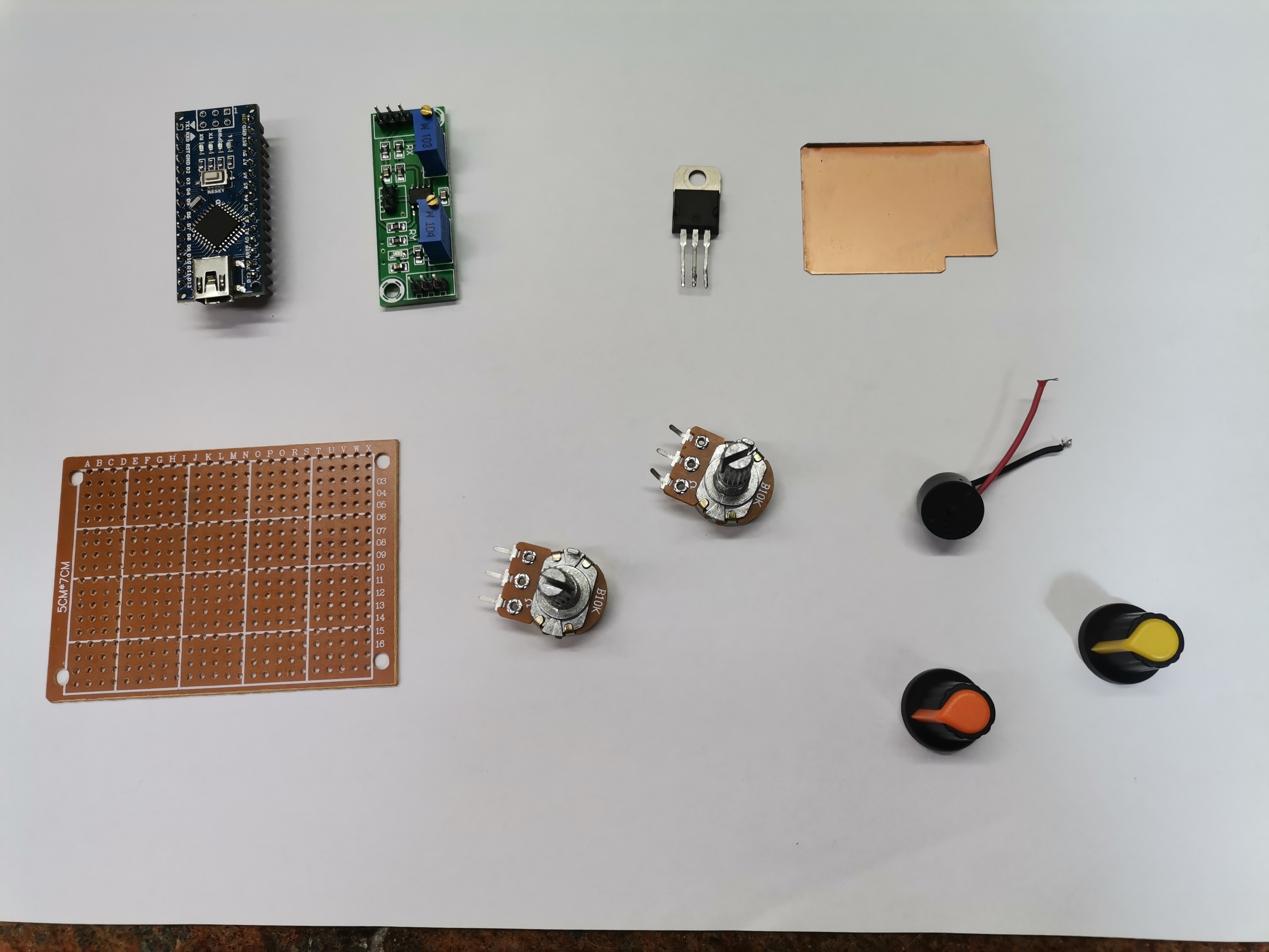
As I mentioned before, the device is relatively simple to build and contains several components:
- Arduino nano microcontroller
- LM358 low signal amolifier module
- Power mosfet transistor (in my case STP65NF06, but you can use any Power mosfet, for example IRF630)
- Two potentiometers 10K ohms
- Buzzer
- Led
- and Double D shape search coils with appropriate capacitors, in this case 1 microF.
To make this project you can order a PCB prototype from PCBWAY. How to order is very easy and you will get 10 Pcs PCB for $5 with very great PCB quality TG150-160.You can design Gerber files for this circuit and upload it on their site ( www.pcbway.com)Generally, shipping of the orders take only 3 to 5 days.

And now a few words about the coils. They consist of 60 turns of 0,4mm^2 (32 s.w.g.) enamelled copper wire coiled in a circle with a diameter of 15 cm. Then they are bent in the shape of the letter D. The wire should be wound close together and kept well bunched and taped to keep it together when removed from the former. Two such coils are required,and both are identical. You will find more about how to wind the coils in my previous videos. The sensitivity of the detector mostly depends on the coils, and especially on their placement. Putting them in an ideal position requires a lot of patience and time, but that is the greatest pleasure in making a device, especially when we achieve the best performance.
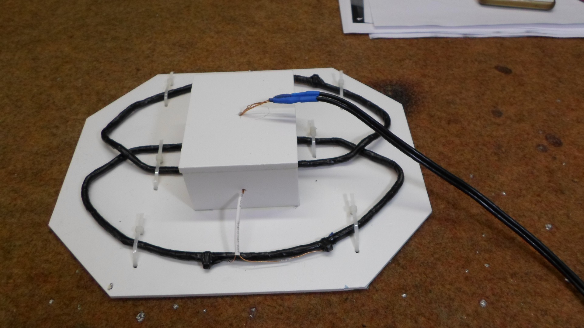
First we need to lightly fix the two coils in the shape as you see in the video. Both potentiometers should be around the middle position, turn on the detector and carefully move the coils to the position where the sound will be lost. Then we move the potentiometers to the position before the sound appears. We are now testing the operation with a larger metal object. This procedure needs to be repeated many times, until we get the greatest sensitivity. In the version with the amplifier module...
Read more »