 mircemk
A seismometer, is an instrument used to detect and record ground motion caused by seismic waves, such as those generated by earthquakes, volcanic eruptions, or other sources of ground vibration. Basically, the seismometer consists of two parts, and one part is a sensor that detects the earthquake and converts it into an electrical signal, and the other electronic part that amplifies, processes and records this weak signal for further processing.

In the previous video , I described a very simple and inexpensive way to make a very sensitive Geophone sensor that is capable of detecting earthquakes from the entire globe. This time I will continue by presenting the electronic part, which together with the sensor will represent a complete home seismometer. During the production I will use a ready-made module and a microcontroller, so there will be no need for extensive prior knowledge and experience in the field of electronics.
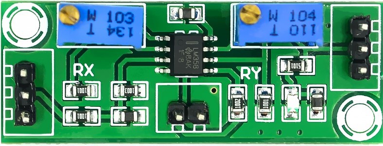
First let's dwell on the amplifier. The signal induced in the sensor coil is very weak, so it needs to be amplified. For this purpose I use small module with LM358 IC which is capable of amplifying weak signals up to 10000 times. We can regulate the gain with these two potentiometers.
This project is sponsored by PCBWay. They has all the services you need to create your project at the best price, whether is a scool project, or complex professional project. On PCBWay you can share your experiences, or get inspiration for your next project. They also provide completed Surface mount SMT PCB assemblY service at a best price, and ISO9001 quality control. Visit www.pcbway.com for more services.

A module like this can be had for a very low price, less than $1 so I avoided making this part. However, if you want, you can make it using a simple operational amplifier IC and few resistors. The two potentiometers of the module were in the middle position and I did not move them at all during the installation, and I precisely defined the amplification of the entire system in the Amaseis software, as I will describe to you later. We test the functioning of this amplifier by gently pressing on the pad, during which a small red LED should light up for a short time.

Next let's focus on the part with the Arduino microcontroller. Namely the signal needs to be processed to remove the noise and unnecessary components, that the filters serve, and then converted to a form that is recognizable by the PC software (converted from analog to digital signal). For this purpose, "nerdaqII" code is uploaded to Arduino.
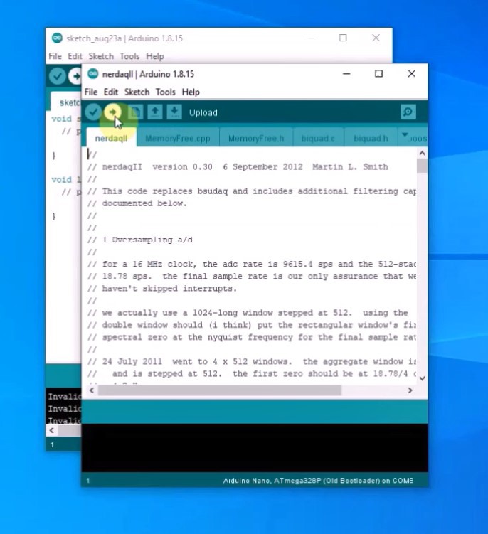
NERdaq is a data acquisition system developed at New England Research to support slinky-based seismometers in schools. The daq is built around an arduino and streams 16-bit (oversampled) values to a usb port; the data are sampled at about 18.78 samples/second. Arduino code is provided for unrestricted use. Installing the code on the arduino follows a standard procedure. In arduino IDE, in tools we select Arduino Nano and a corresponding com port. Then we go to open and locate the folder with the nerd software and select the nerdaqII.ino file. Now we press the upload button and when it's done, the part with the Arduino is done. The consumption of the whole assembly is very low, so there is no need for an external power supply, but it is powered through the USB port of the computer. The signal from the Arduino microcontroller through the USB-to-Serial port is transmitted to the Amaseis PC software. This software actually performs signal visualization as well as its logging for further processing.

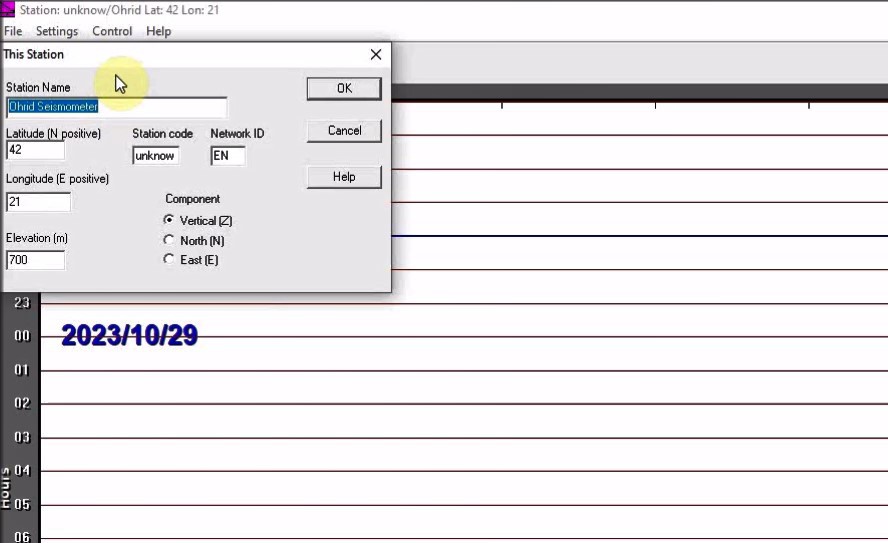
Now we need to install the Amaseis software.Then we start it and go to settings - this station - and enter the name, and latitude and longitude of the place.
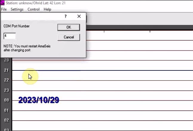
- Next, in the settings - COM port - we enter the COM port to which the Arduino is connected, in our case it is COM4.
- Then, in setings - device - we select SETUPK1,
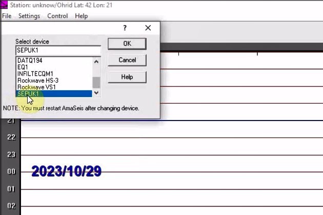
and in SET Zero Level we...
Read more »
 Angeliki Beyko
 jean.perardel
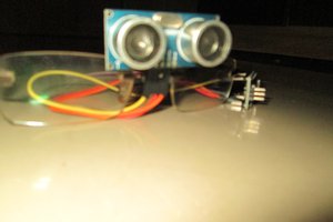
 Debargha Ganguly
 Jesse R