 Ted Yapo
I started building the VGA generator hardware yesterday. The main ICs are all SOIC (and SOJ for the SRAM), so I had some adapter boards made to mount over a solid ground plane. The adapters all have bare copper (gold) on the back, and I thought about reflowing them to the plane, but I ended up just soldering down the castellations on the edges. Hopefully, this will be good enough.
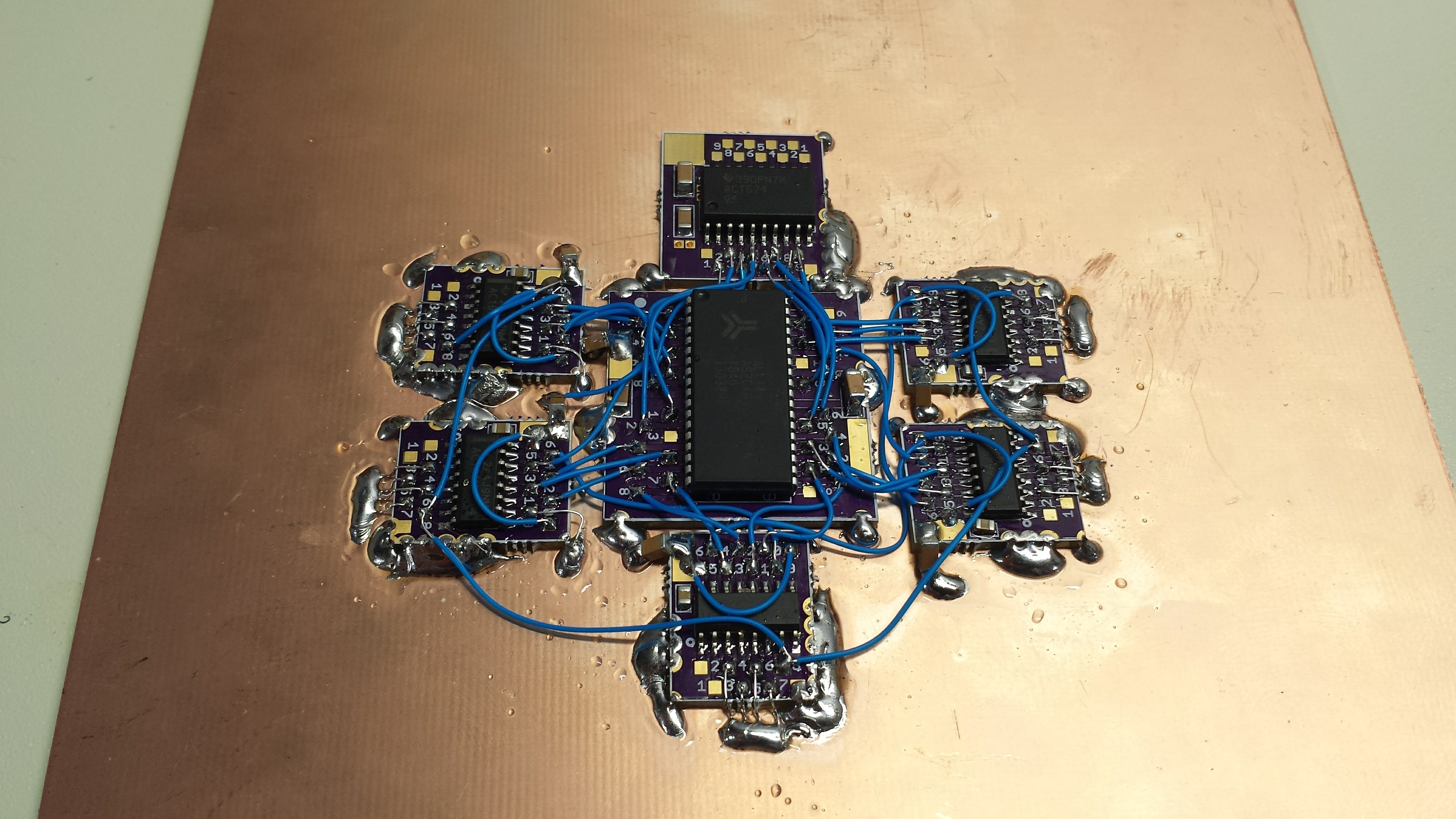
The center IC is the 512k x 8 SRAM, and the five 74AC163 address counters are in the outside ring to minimize the wire length. The 74AC574 output latch is at the top. Obviously more to build, but it's a start. I haven't run the power buses yet - there are 0.1 uF and 10 uF MLCCs at each IC so I think I can be somewhat casual with the 5V supply wiring.
I finally bought a copy of High Speed Digital Design: A Handbook of Black Magic which I have been meaning to read forever. I found an "international" paperback edition for less than $25. To comply with the warning label on the back, I only read it when I am in India, Bangladesh, Pakistan, Nepal, Sri Lanka, the Maldives, or on Tralfamadore.
At any rate, the book covers why this thing might not work - if the edge rates of the 74AC logic are fast compared to the wire lengths. I have read that the 74AC gates have rise times of 2ns, but I measured them at 1.15 ns here on my 300 MHz scope, which is really, really close to the rise time of the scope itself. In a cable with velocity factor 1, the edge would cover about 35cm of wire; a conservative design might treat any wires less than about 1/6 of this ( = 6 cm) as transmission lines, and terminate them appropriately. Even for wires shorter than this, inductance of the line combined with the capacitance of the receiving gate can cause ringing and signal problems.
I've decided to take a chance with unterminated wires for the address lines - they're only 1 or 2 cm at most, and fairly close to the ground plane. I'm guessing they're OK. The two really critical signals on the board are clock and reset - for these, I'm going to run twisted-pair lines to each counter from dedicated 74AC244 buffers, and source-terminate the drivers.
I made some twisted pair with 30ga kynar wire-wrap wire, and measured it's impedance at around 102 ohms with a simple time-domain-reflectometer setup. (I also measured the capacitance of a section of line, then shorted one end and measured the inductance - this gave 107 ohms - close enough). If I source-terminate these lines, I should be able to make the clock wires as long as I need.
The one thing I'm not sure about is the TC outputs from counter to counter - the long wires seen above. These aren't edge-triggered, so reflections should not be a problem as long as ringing has died down before the next clock edge. If I have to, I can replace them with sections of twisted pair, or maybe just replace each wire with a 100-ohm resistor to damp any ringing.
There's still a lot of work to do on this board, but I got it started, at least.
Discussions
Become a Hackaday.io Member
Create an account to leave a comment. Already have an account? Log In.