 Ted Yapo
I finished assembling the board. Even armed with the datasheets for all the IC's, you wouldn't find the bug in this rat's nest:
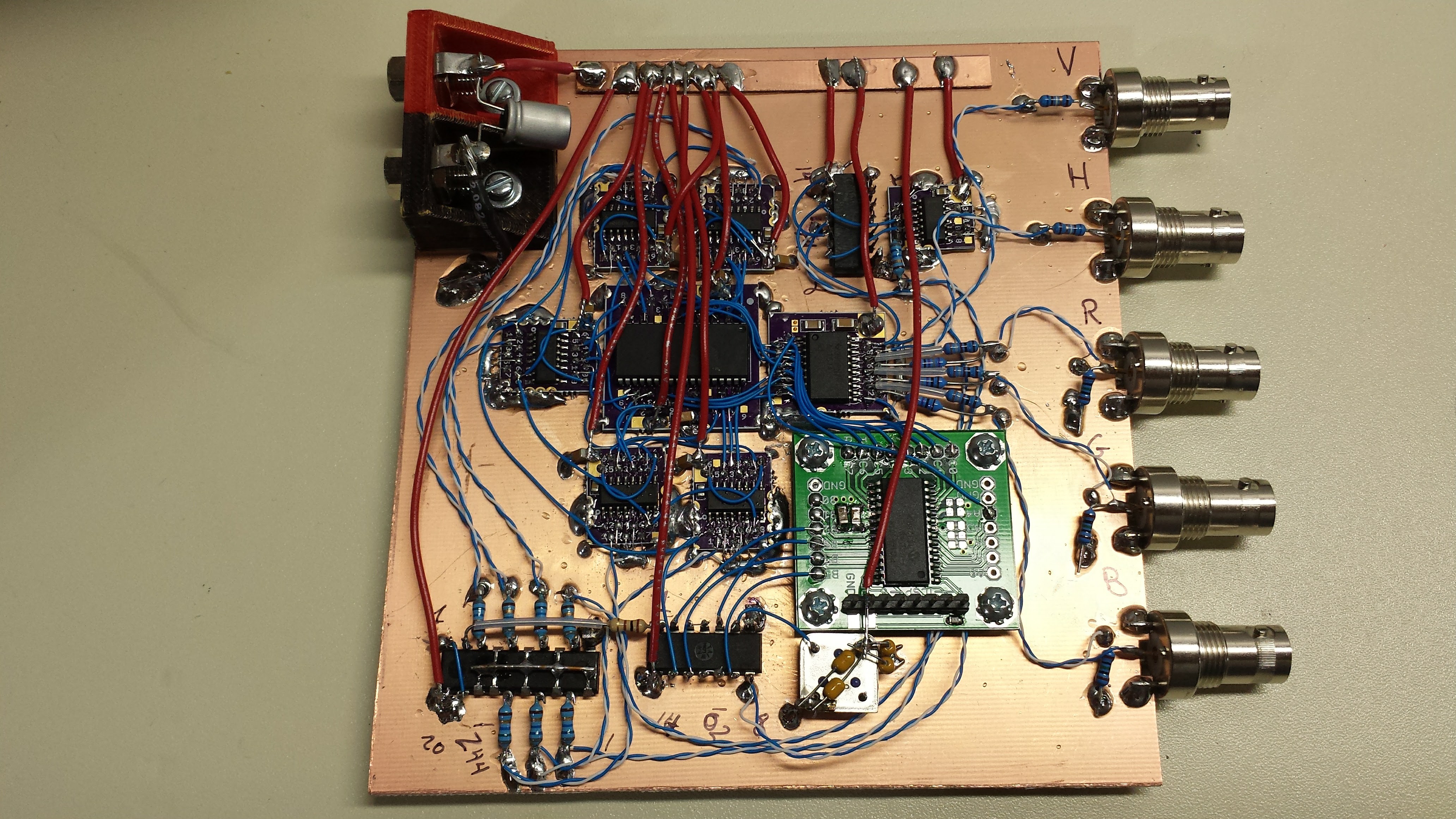
...and that's because the bug is in the 74AC163 datasheet itself! Fairchild was kind enough to include the following diagram in the datasheet:
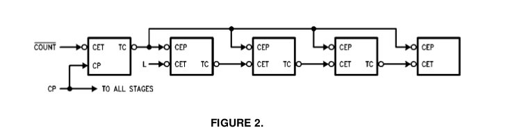
See that "L" into the CET input of the second stage? Of course, you're supposed to know that those damn logic guys with their put-useless-bubbles-everywhere habits really mean that you should supply an "H" to the CET input on the chip, because the bubble really isn't there, it's just a convention. Just like the useless bubbles on the output of TC and input of CEP - you're supposed to ignore those and just wire TC to CEP, not wire two inverters external to the chip.
The whole mess is clarified by the supplied table:
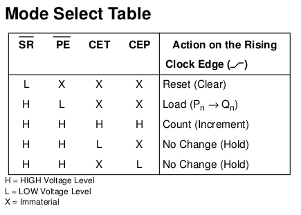
here, it's easy to see that everything needs to be high for the count to proceed.
Once I fixed that, I got the counters running well at 25.175 MHz. So far it looks pretty good - the MSB transition is within a few nanoseconds of the LSB, and the twisted-pair clock distribution scheme seems to give nice clock signals at each of the seven IC's that require it.
Now, it's software time again.
EDIT 20170101
Contrast the above diagram with this one I scanned from my copy of the Signetics TTL Logic Data Manual 1982:
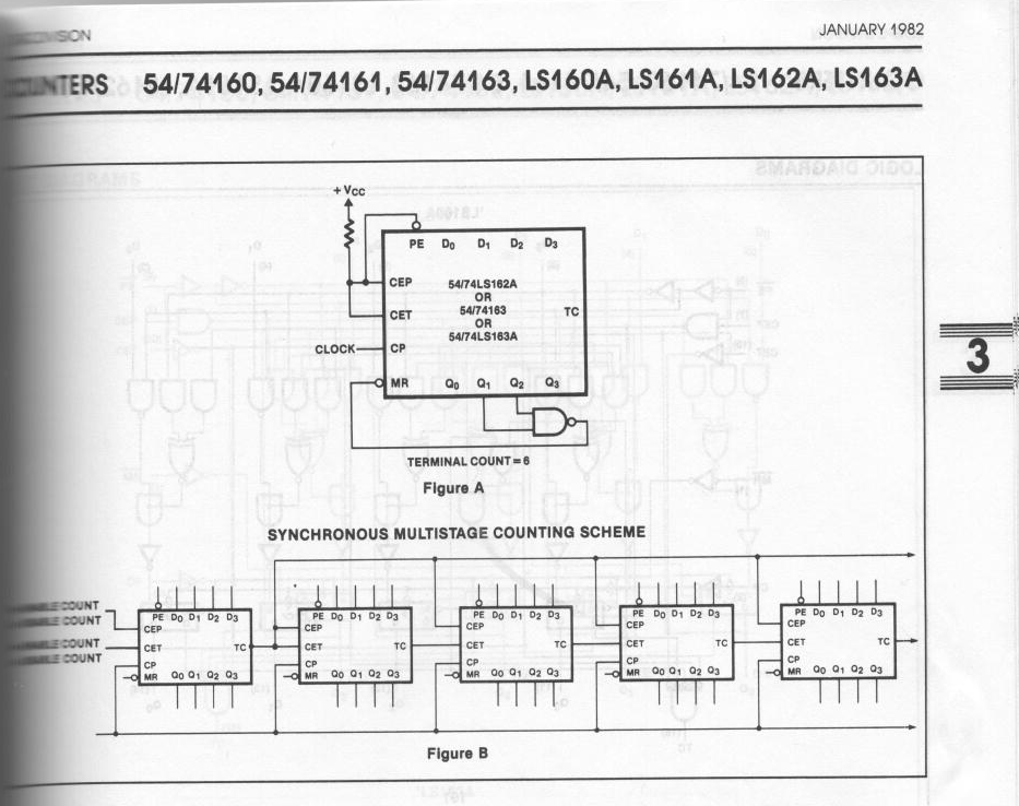
Much clearer - I could have even understood it at age 12, when this was printed :-)
Discussions
Become a Hackaday.io Member
Create an account to leave a comment. Already have an account? Log In.
[this comment has been deleted]
I guess some of the software conventions I follow must look equally goofy to hardware engineers, but I really could never get into this crazy bubble stuff. Every time I try to read a good explanation of it, they seem to make it more complex. It's especially troublesome when the device boundary isn't clear - in the example above, the bubbles are all external to the five 74AC163 packages shown, and of course, none of them are necessary because they all cancel out (except for the one tied low, which is really the IC input tied high).
Are you sure? yes | no