J Gleyzes
-
Quick Update 03/10/22
10/03/2022 at 20:10 • 0 comments![]()
Currently, I am checking the new PCB and changing the code. As soon as it's ready I'll publish it.
Corrections:
![]()
There were2 errors on my PCB one on the pin of the DHT22 and one on the 5V pump which consumed too much power for the 2N7000. Everything is corrected now and explained into this log and in the files. The 2N7000 has been replaced by the TN0604N3-G mosfet.
Mist generation:
If you have been following the project from the beginning, there was a change on the last PCB. I don't use a mosfet driver anymore because I finally found a mosfet (FQB19N20LTM) that works directly with the pins of the esp32.
Proof in video :
The android application:
The application will be ready very soon, I still need to fix some bugs. The app will allow to modify all the parameters of the tower and to read the pH, EC and temperature sensors.
I'm not sure about the design yet, 3 versions at the end of the video. If you have any better idea don't hesitate !
-
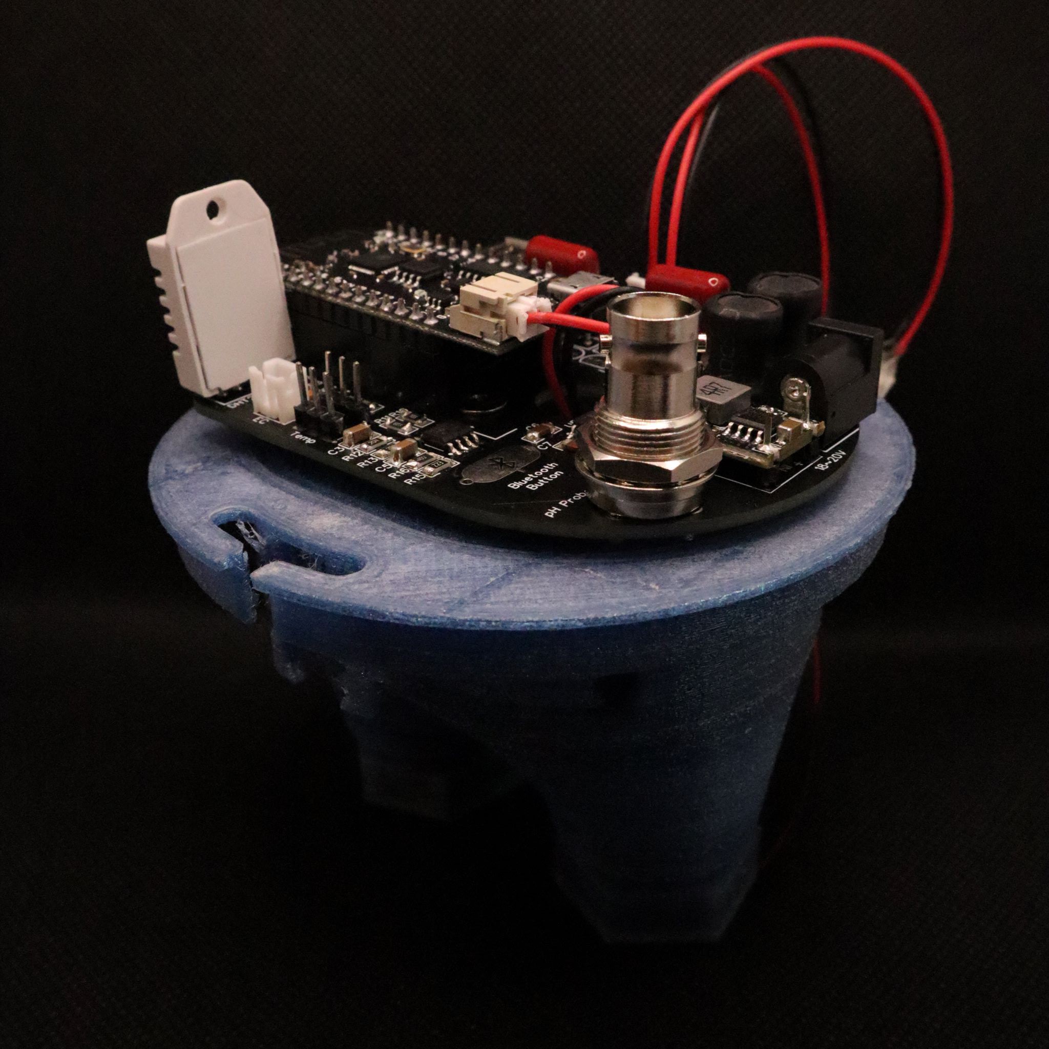
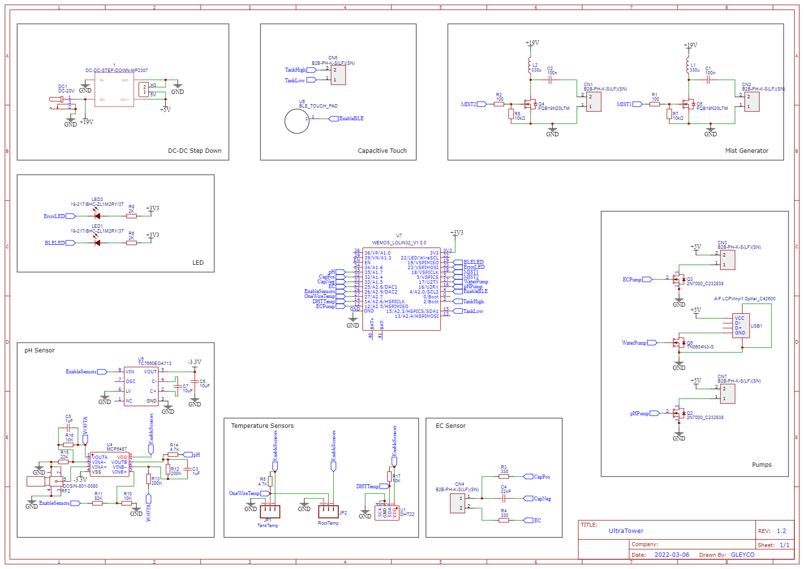
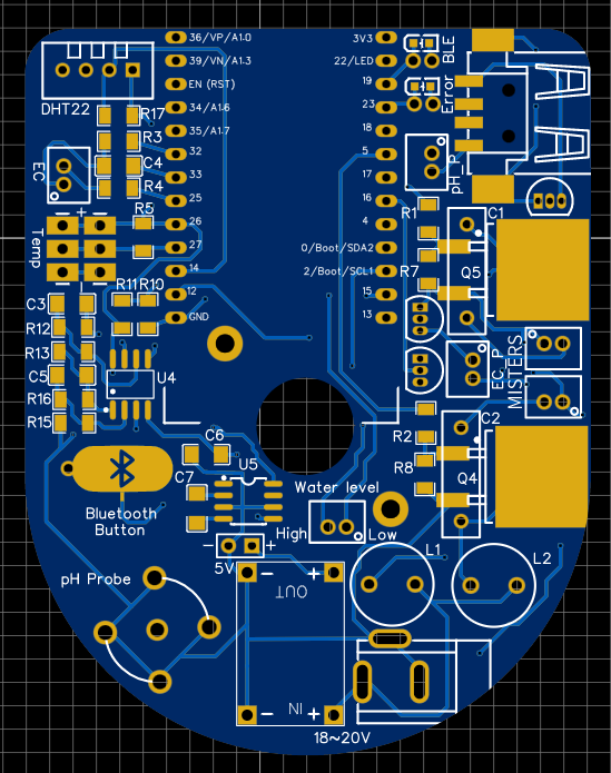
Final PCB : Cost and Modularity
10/01/2022 at 08:40 • 1 comment![]()
This latest version of the board allows you to choose what you want to monitor in the tower. This board has been designed to be modular to suit your needs.
We will look at each module one by one:
Main module :
This module is mandatory. It is the brain of the tower with the ESP32 and it is the one that allows the power supply of the board, the generation of the fog and the filling of the small tank thanks to the pump.
Component Quantity Cost Link PCB 1 1.6€ Lolin 32 Lite 1 2.85€ Aliexpress CN3903 5V 3A
DC-DC Step down1 0.49€ Aliexpress Capacitor 400V104J 2 0.12€ TN0604N3-G 1 1€ DC Charger connector 1 0.2€ 18-20 V Charger 1 12€ 330uH coil 2 0.32€ 100 ohm resistor 2 0.025€ 10K ohm resistor 2 0.025€ FQB19N20LTM 2 1.81€ Onsemi Mini JST 2.0 PH 3 0.088€ Usb Pump connector 1 0.3€ 5V Pump 1 10€ Aliexpress 108kHz Disk 2 2€ Aliexpress EC module:
This module allows you to know the mineral concentration of the solution. Optional module.
Component Quantity Cost 330 ohm resistor 2 0.025€ 22nF capacitor 1 0.013€ Mini JST 2.0 PH 1 0.088€ EC probe 1 1€ pH module:
This module allows the acidity of the solution to be known, given that a pH between 5.5 and 6.5 is desired. This module is optional.
Component Quantity Cost Link MCP6487 1 0.4€ Microchip TC7660 1 0.99€ Microchip BNC connector 1 0.73€ Aliexpress pH probe 1 11€ 200k ohm resistor 2 0.025€ 10k ohm resistor 2 0.025€ 22K ohm resistor 1 0.025€ 82k ohm resistor 1 0.025€ 4.7k ohm resistor 1 0.025€ 1uF capacitor 2 0.013€ 10uF capacitor 2 0.013€ Temperature module:
It provides information on the temperature of the ambient air, the root chamber and the water in the main tank. It also compensates for pH and EC sensor values that are correlated to the water temperature. This module is optional. You can also use a single sensor depending on your needs.
Component Quantity Cost DHT22 1 2.46€ DS1820 2 2€ 10k ohm resistor 1 0.025€ 4.7k ohm resistor 1 0.025€ Conclusion:
The electronics of the tower cost 61.4€ with all the modules but it works with only the main module which costs 36.4€. You can reduce the price by recycling an old laptop 18-20V charger.
This PCB can also control 2 additional pumps to adjust the pH and nutrient concentration. But I haven't implemented this in the code yet.
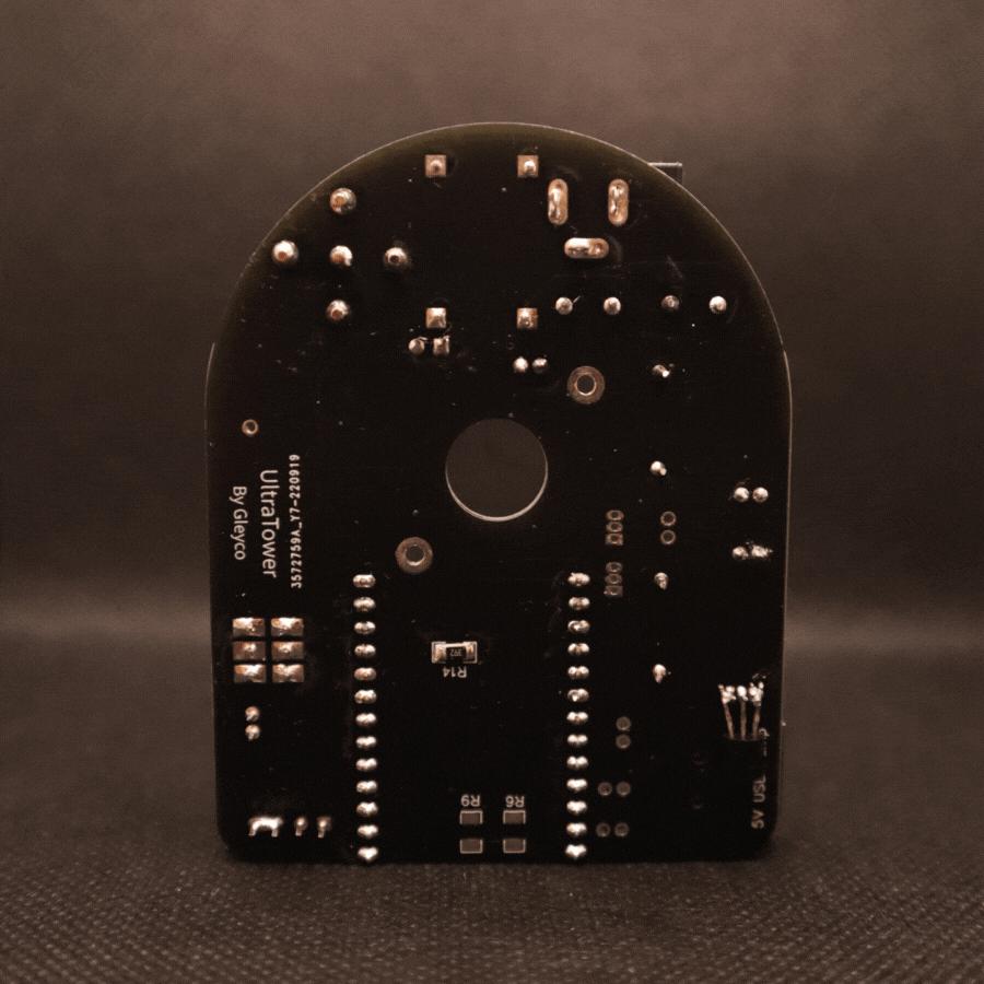
You can find the gerbers in the project files. (gerber_PCB_final)
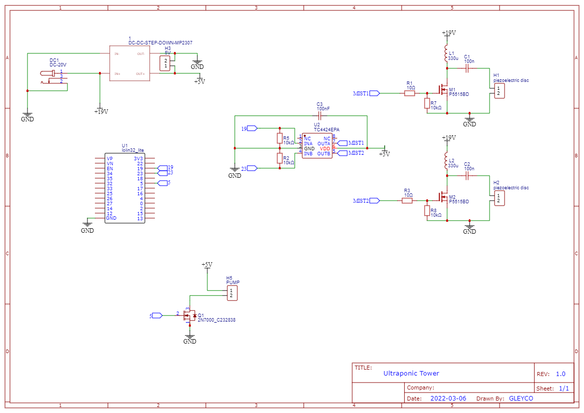
Schematic:
![]()
-
Quick Update 22/09/22
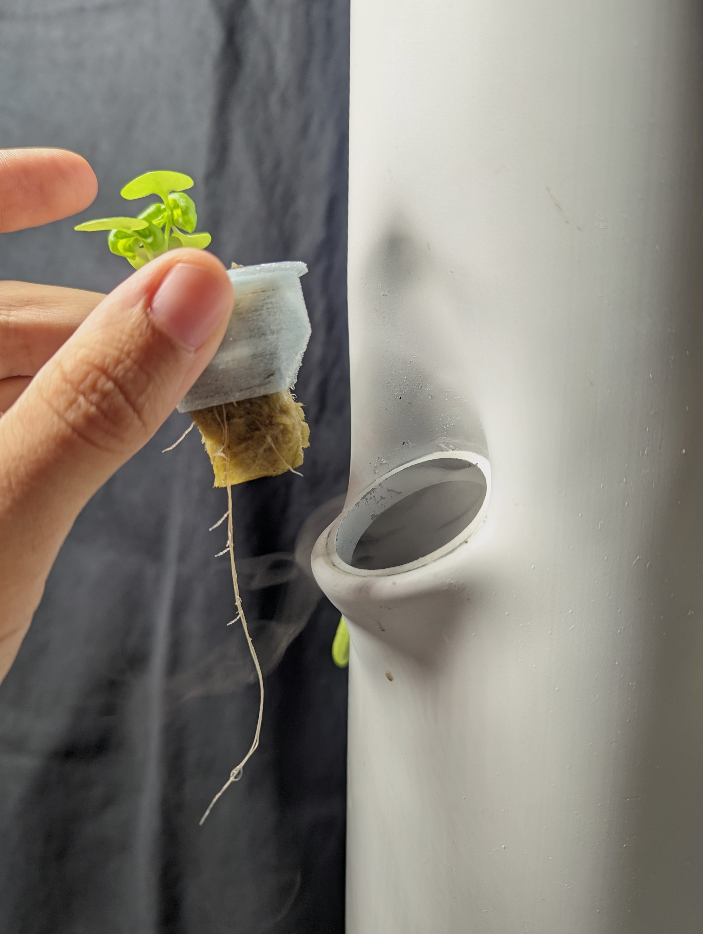
09/22/2022 at 12:15 • 0 commentsThe new tower and the pcb are being tested for 2 weeks now. Everything is working great.
![]()
On the picture you can see a 3 weeks old basil plant, with 2 weeks in the tower. You can also see the fog coming out of the tower. The roots are growing and are white, which is perfect. The watering cycle is 10 min ON with 1 mister and 5 min OFF.
The solution was at 1 EC during the 2 weeks I just adjusted it to 1.5 EC.
As the prototype PCB is working and the circuits of the different sensors are operational (pH, EC, Temperature), I just ordered a PCB with all the components. I am waiting for the delivery to be able to test it.
![]()
-
pH Sensor
09/17/2022 at 09:25 • 0 comments
pH is important in hydroponic systems, indeed depending on pH of the solution certain minerals will be more or less accessible for the plants.![]()
This is why monitoring pH is essential to optimize plant production. The ideal range is between 5.5 and 6.5 pH. pH can fluctuate, which is not important, but it should not deviate too much from this target range.
That is why we will add a pH sensor to the tower and maybe later a pump to regulate the pH automatically.
pH sensor circuits already available on internet have 5V outputs that are not suitable for the ESP32 and the only one that outputs 3.3V is over 40€.Let's make one.
Specifications:
- The sensor must be accurate and stable enough
- It must be powered by 3.3V
- Output value must be between 0V and 1.2V, the ADC of the esp32
- pH measurement should span at least between 4 and 9.
The probe:
First, let's talk about the pH probe. It is immersed into the solution and gives a value between -0.414V and 0.414V depending on pH.
![]()
This value will have to be amplified and shifted to purely positive values. Indeed the ESP32 can have a maximum value of -0.3V on its pins otherwise the ESP32 is damaged and the ADC can only handle DC positive values.
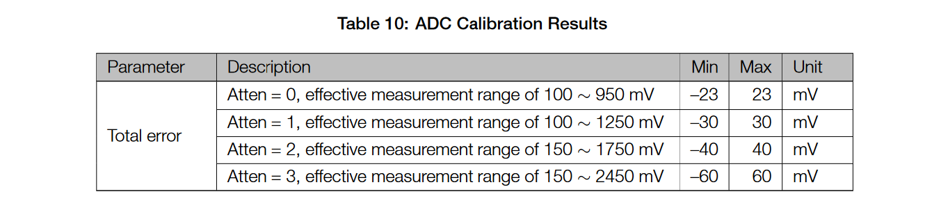
The ESP32 ADC:
![]()
I have chosen level 1 attenuation which allows me to have precise values between 100mV and 1250mV. With these values the pH7 should be centered at 700mV (1200mV/2 + 100mV).
Now we have to think about the protection of the ESP32, the lowest value should not be below 0V. Even if it is not useful for UltraTower to measure a pH of 0, you never know and it is better to secure this factor.
So the lowest value should be 50mV at pH0, so there is 650mV between ph7 (700mV) and pH0 (50mV). We can calculate the gain X that we want:
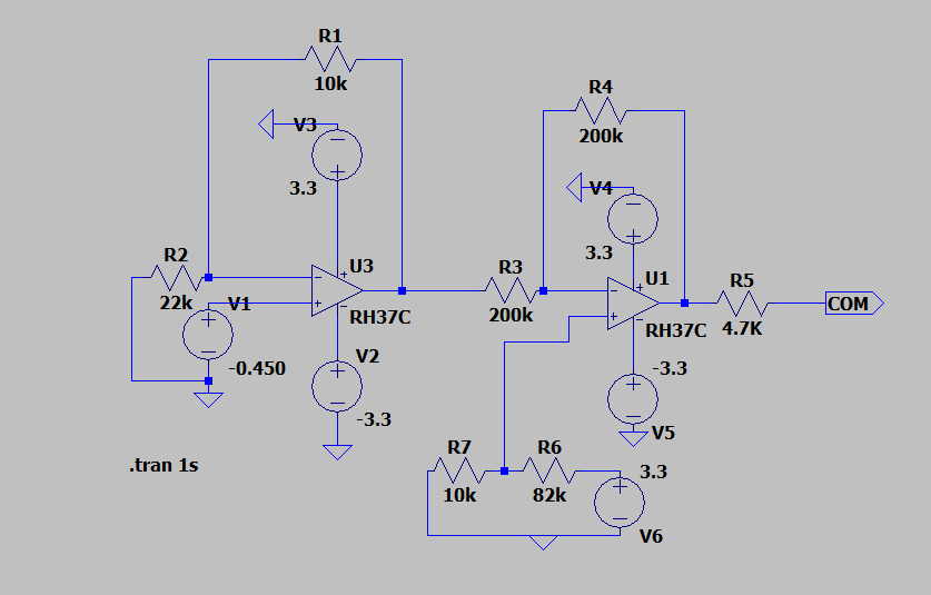
Test on LTSpice:
![]()
Here are two operational amplifiers to convert the +/- 450mV of the ph probe (V1) to an output of 0 to 1.3V for the ESP32 ADC (COM). The first opAmp is a non-inverting amplifier with a gain of 1.44 with the 2 resistors:
With standard resistors values we get a gain of 1.45.
The second opAmp is a Differential Amplifier with a gain of 2 so I set the divider bridge at the bottom of the schematic to 350mV (700mV/2).
LTSpice simulations show that for pH0 (probe set to 0.450mV) COM is at 0.80V and for pH14 (probe set to -0.450mV) COM is at 1.35V.
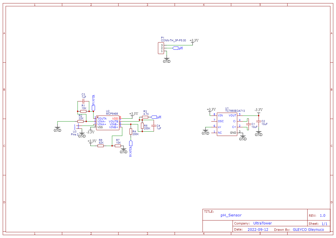
These two extreme pH values will not be read by the ESP32 ADC which is between 100mV and 1250mV but they will not damage the ESP32. The range of values we are interested in is between pH4 and pH9.Schematic:
![]()
The MCP6486 is a Dual Operational Amplifier that allows to use a single chip. It needs to be powered at 3.3V and -3.3V. The -3.3V supply is provided by the TC7660 which needs only two capacitors to operate.
PCB:
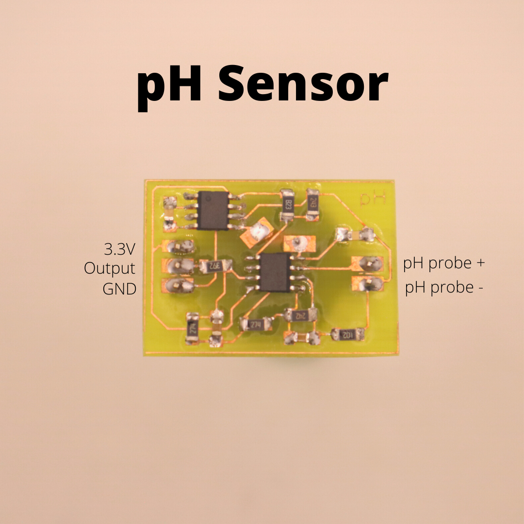
![]()
The output value changes when the probe is placed in different solutions. This circuit works, you just need to add a calibration so that the ESP32 knows what pH the solution is.
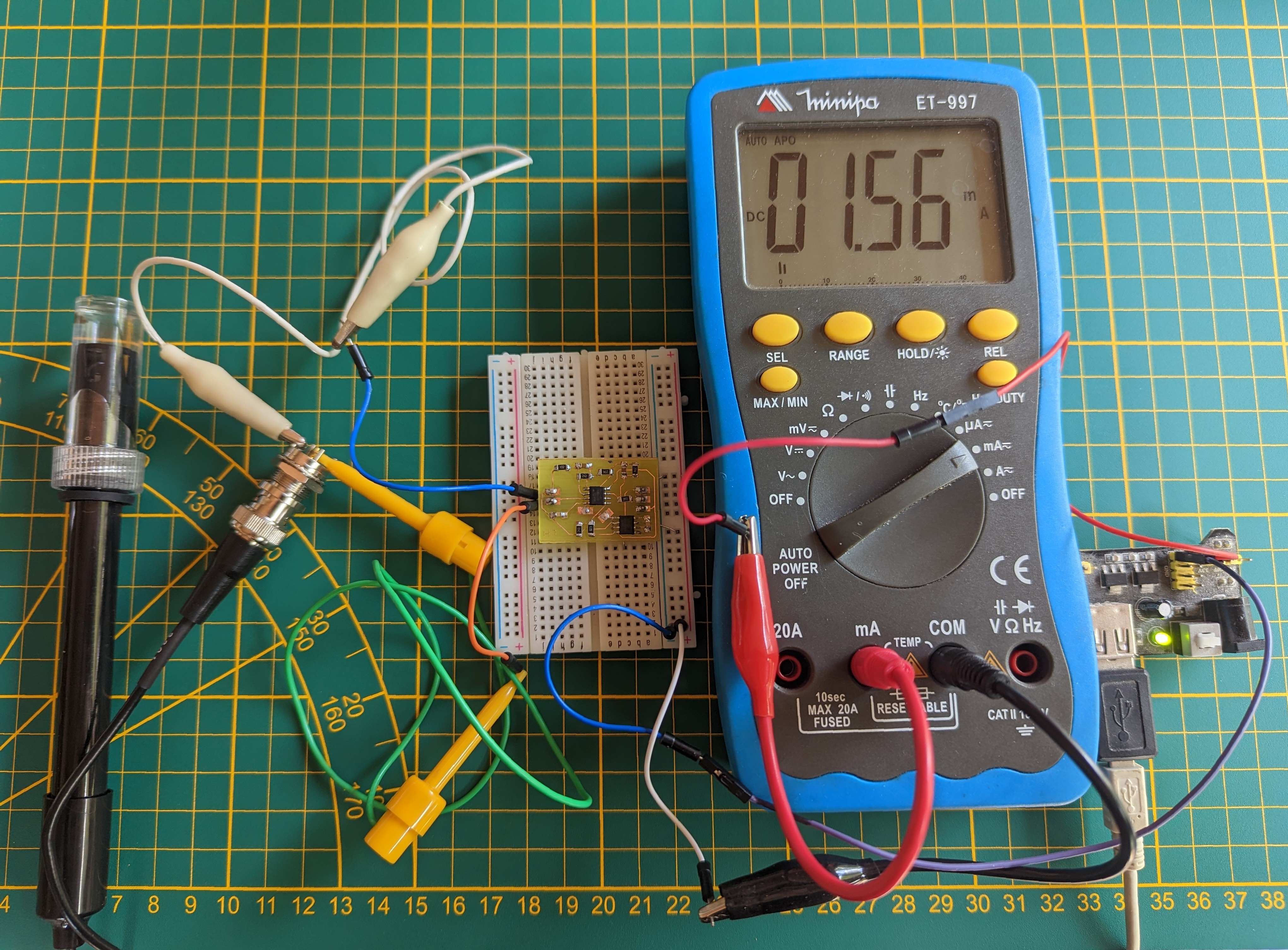
The power supply for the circuit is 3.3V at 1.56mA so it can be powered on and off via a pin on the esp32 to preserve the pH probe for as long as possible.
![]()
All the sensors in the functionnal block diagram are operational, now I have to make a PCB to put it all together.
-
Improvement of the EC sensor
09/12/2022 at 07:03 • 0 commentsIt is better to read the EC sensor log before reading this one.
I wanted to test the stability and accuracy of the EC sensor!
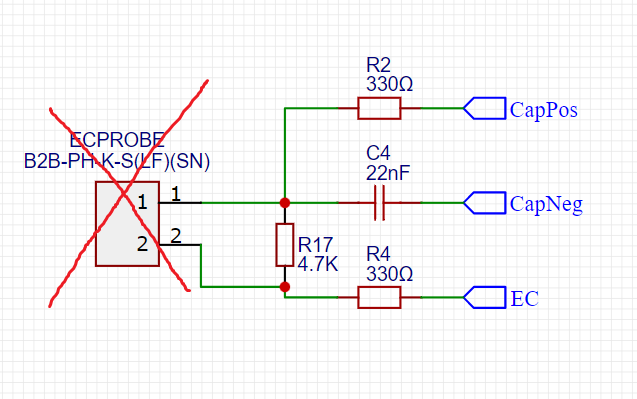
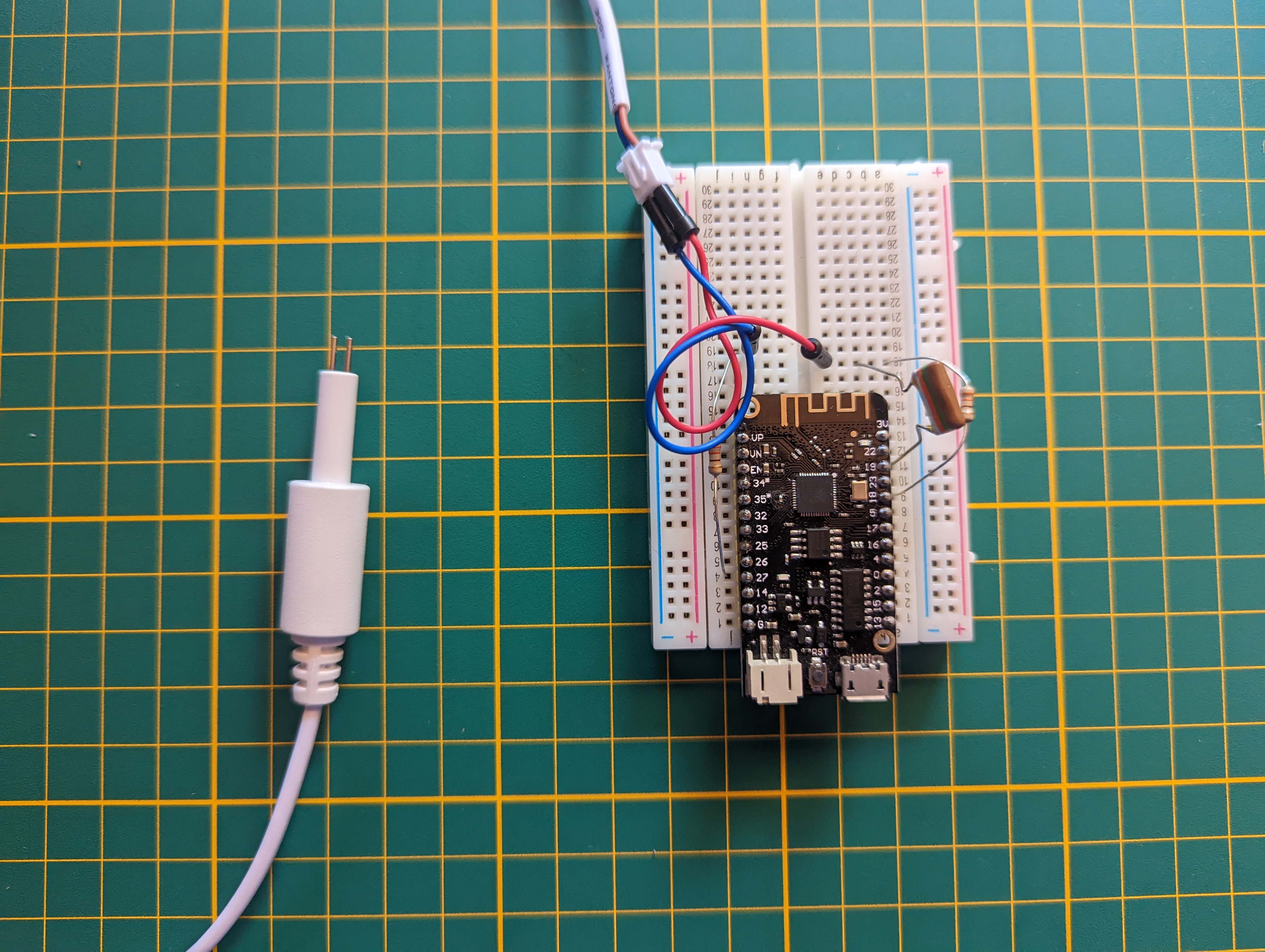
So I replaced the EC probe with a fixed resistor (to mimic the resistance of a solution).
![]()
The EC probe was replaced by R17 a fixed resistor for testing.
Code
You can find the whole code in this log but what we are interested in today is the measurement part:
  ///////////////////////////////////////////////////////////////////////
    // Stage 2: measure positive discharge cycle by measuring the number of clock cycles it takes
    // for pin CAPPOS to change from HIGH to LOW.
    // CAPPOS: input.
    // CAPNEG: output, low (unchanged).
    // EC: output, low.
    endCycle = 0;
    startTime = micros();
    pinMode (CP_PIN,INPUT);
    startCycle = ESP.getCycleCount();

    attachInterrupt(CP_PIN, isrCountEndCycle, FALLING);

    digitalWrite(EC_PIN, LOW);

    pinMode(EC_PIN, OUTPUT);

    while (endCycle == 0) {                   // endCyle gets set in the ISR, when an interrupt is received.
      if (micros() - startTime > EC_TIMEOUT) { // Time out - in case sensor not connected or not in water.
        timeout = true;
        break;
      }
    }
    detachInterrupt(CP_PIN);
    if (timeout) break;
    dischargeCycles = endCycle - startCycle;
    totalCycles += dischargeCycles;
Explaination line by line :
startCycle = ESP.getCycleCount();
This is where the measurement of the CPU cycles number starts. This function is useful for accurate timing of very short actions.
attachInterrupt(CP_PIN, isrCountEndCycle, FALLING);
A function is attached which is triggered when the capacitor is empty. This is done by the CP_PIN. Once it is triggered it executes this line:
endCycle = ESP.getCycleCount();
This is the end of the measurement which also allows you to exit the while() loop.
Then we detach the CP_PIN from the function and calculate the number of CPU cycles.
digitalWrite(EC_PIN, LOW);
pinMode(EC_PIN, OUTPUT);
These two lines are used to ground the EC_PIN to discharge the capacitor through the probe immersed in the solution (variable resistance depending on the nutrient concentration).
startTime = micros();

*
*
*

if (micros() - startTime > EC_TIMEOUT) {
        timeout = true;
        break;
 }
These lines allow you to exit the while() loop if the probe is not immersed in water.
Test to measure accuracy:
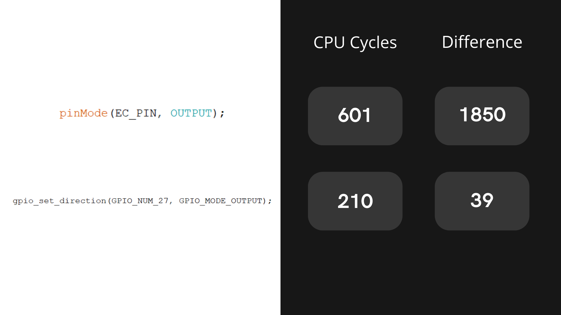
For the accuracy test I took 500 measurements of a fixed resistor of 4.7kOhm and calculated the difference between the lowest and highest value. The result is that the values can have a difference of 2000 cycles which is not accurate at all. Each line of code after the startCycle = ESP.getCycleCount() can vary the measurement so I took each arduino function and compared it with the similar Espressif.'s function
For each function we measure the execution time in cycles and if there is a difference in cycles over 500 measurements, here is the result:
![]()
We can see that the Espressif's function takes 3 times less cycles to run but both functions are very stable there is no difference in cycles over 500 measurements.
![]()
Here we can see a big difference, the arduino function can have a big variation in execution cycles.
We will fix this!
The new code:
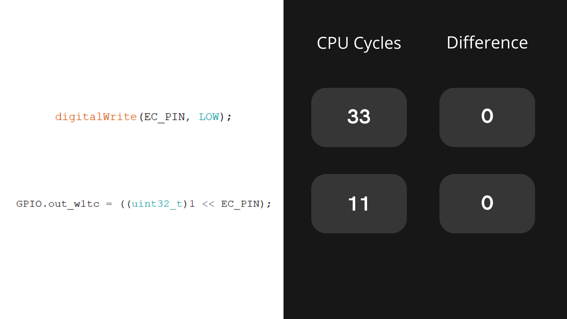
 ///////////////////////////////////////////////////////////////////////
    // Stage 2: measure positive discharge cycle by measuring the number of clock cycles it takes
    // for pin CAPPOS to change from HIGH to LOW.
    // CAPPOS: input.
    // CAPNEG: output, low (unchanged).
    // EC: output, low.

    endCycle = 0;
    pinMode (CP_PIN,INPUT);

    timerEC = timerBegin(2, 80, true);
    timerAttachInterrupt(timerEC, &onTimer, true);
    timerAlarmWrite(timerEC, EC_TIMEOUT, false);
    timerAlarmEnable(timerEC);

    attachInterrupt(CP_PIN, isrCountEndCycle, FALLING);

    startCycle = ESP.getCycleCount();
    GPIO.out_w1tc = ((uint32_t)1 << EC_PIN);
    gpio_set_direction(GPIO_NUM_27, GPIO_MODE_OUTPUT);

    while (endCycle == 0) {           // endCyle gets set in the ISR, when an interrupt is received.
    }

    timerDetachInterrupt(timerEC);
    detachInterrupt(CP_PIN);
    timerEC = NULL;


    if(endCycle == -1){
      timeoutStop = true;
      break;
      }

    dischargeCycles = endCycle - startCycle;
    array[i] = dischargeCycles;
I re-tested the 500 measurements of a fixed 4.7kOhm resistor and calculated the difference between the lowest and the highest value which gives us a difference of 200 cycles.
The improvement is enormous.You will notice that there are no more lines of code inside the while() loop, this is great for cycles count accuracy but it must stop if the EC probe is not in a liquid.
The stop is realized by the timerEC which executes the function onTimer() after 2000 microseconds:
hw_timer_t *timerEC = NULL;

void IRAM_ATTR onTimer(){
     endCycle = -1;
}
To further improve the accuracy I fill in an array of the 500 values then I sort them in an increasing order and finally I average them by removing the first 100 values and the last 100. This gives us a variability of 3 cycles!
Conclusion:
The arduino functions are great for reading code but for accurate and fast code execution it is sometimes better to go without.
We went from a max variability of 2000 CPU cycles to a max variability of 3 cycles! Perfect!
Code for sorting and average:
#define NUM_OF_READ_SENSOR_AVG 500 #define NUM_OF_READ_TO_DELETE 100 int32_t moyenneOfArray(int16_t *ar){ int32_t avg = 0; int16_t nb = NUM_OF_READ_SENSOR_AVG - NUM_OF_READ_TO_DELETE; for (int16_t i= NUM_OF_READ_TO_DELETE; i< nb; i++){ avg += ar[i]; } return avg / (NUM_OF_READ_SENSOR_AVG - 2*NUM_OF_READ_TO_DELETE); } void quickSort(int16_t *ar, int16_t n){ if (n < 2) return; int16_t p = ar[n / 2]; int16_t *l = ar; int16_t *r = ar + n - 1; while (l <= r) { if (*l < p) { l++; } else if (*r > p) { r--; } else { int t = *l; *l = *r; *r = t; l++; r--; } } quickSort(ar, r - ar + 1); quickSort(l, ar + n - l); } -
Temperature sensors
09/10/2022 at 08:56 • 0 commentsTemperature is important in soilless cultivation. Articles agree on an ideal growing temperature between 18°C and 26°C. A too cold temperature will slow down growth but increase the dissolved oxygen in the water. While too hot temperature will increase bacteria and disease in the plants.
It should be noted that pH and EC are correlated with temperature, so the values of these two sensors must be corrected.
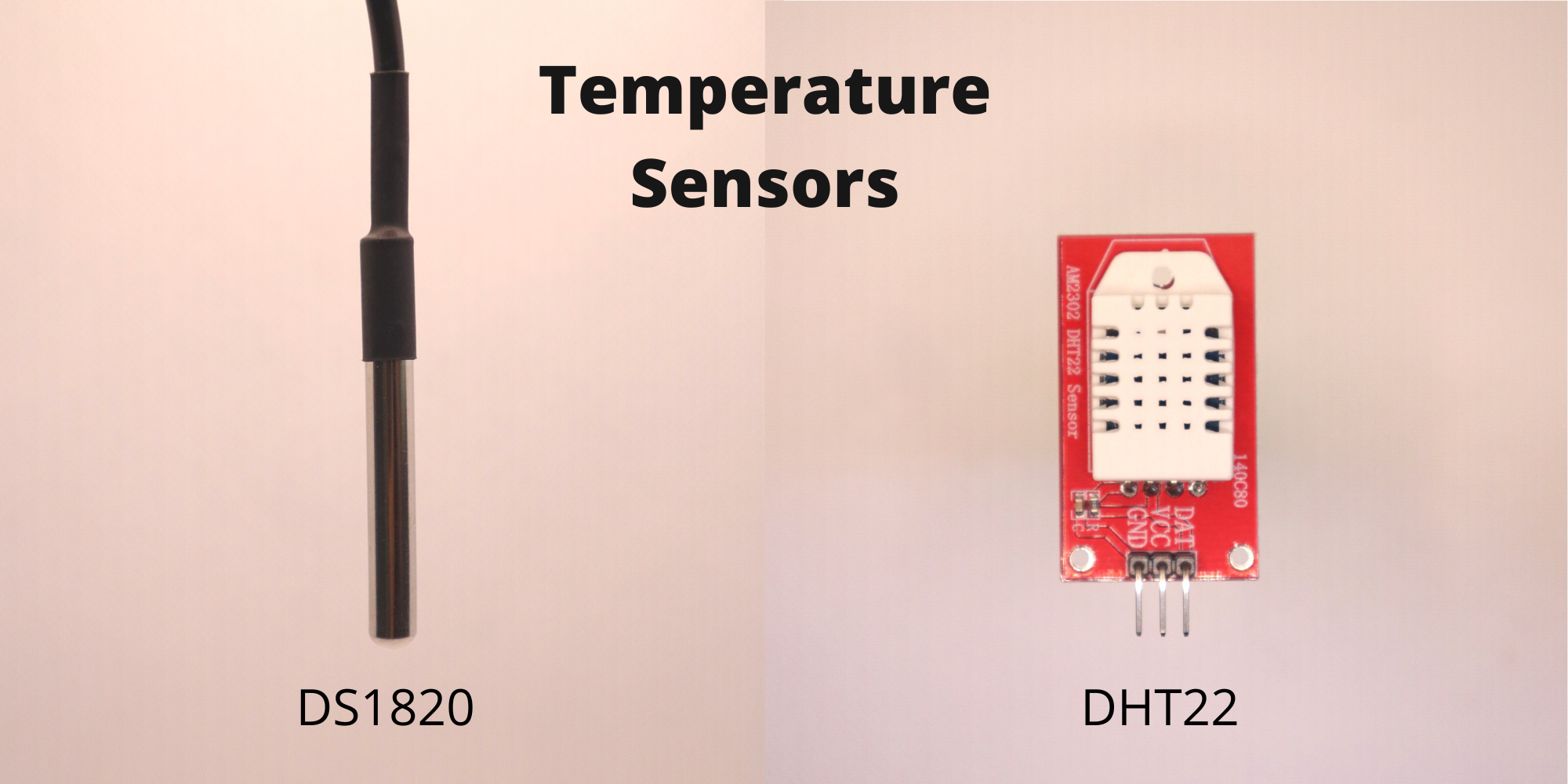
It is therefore essential to monitor the water temperature, which is why I will be adding 3 sensors to the UltraTower. There will be two DS1820 waterproof temperature sensors one located in the main tank and one in the root chamber. The third sensor is the DHT22 which will be located at the top of the tower to monitor the ambient air temperature and humidity.![]()
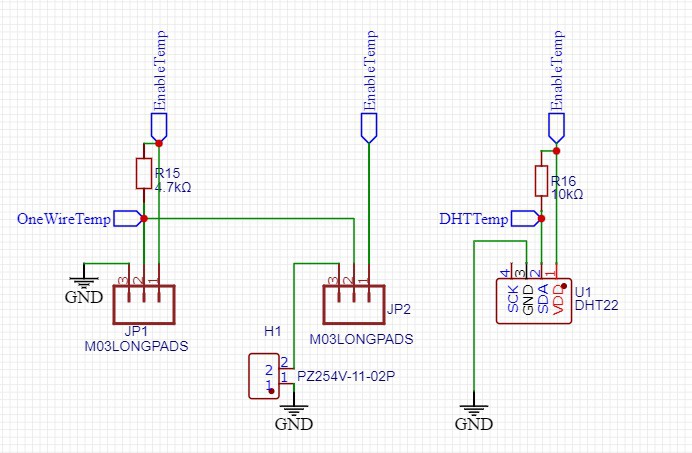
Schematic:
For energy saving reasons, the sensors should not be active continuously but only when needed. Both types of sensors are compatible with the 3.3V of the ESP 32.
If we look at the datasheets a DS1820 sensor consumes 1.5 mA in active mode and the DHT22 consumes a maximum of 2.1 mA. This gives us a total of 5.1mA which is largely supported by one pin of the esp32 which can deliver 40mA.
Therefore, we only need 3 pins, one to power up all the sensors and switch off when not using it, one for the one wire technology of the DS1820 that allow us to read the both sensors with only one pin and the last pin is use to read the DHT22.
![]()
I'm not going to detail the code in this log as it is quite simple to read the sensors. You can look at the examples of the 3 libraries that I use for these sensors:
- DHT22: DHT (MIT License)
- DS1820:
- DallasTemperature (MIT License)
- OneWire (Copyright (C) 2000 Dallas Semiconductor Corporation, All Rights Reserved. / Free to use)
The tower now has an EC sensor, the temperature sensors. The pH sensor is missing to finish the water quality block.
-
EC Sensor
09/05/2022 at 19:06 • 0 commentsEC is the abbreviation for Electro Conductivity. It is used to determine the nutrient concentration of the solution. This factor is essential to optimize the soilless culture. Indeed, the nutrient concentration will not be the same for a seeding as for a flowering plant, or lettuce needs less nutrient than tomatoes.
Let's get started! Let's add an EC sensor to UltraTower.
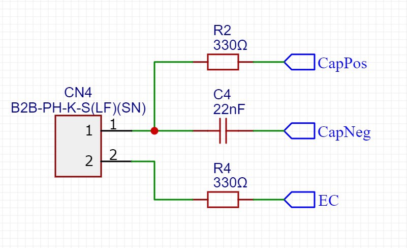
There are many EC sensors on the internet ranging from 10€ to over 200€. We will make one with 4 components + the ESP32.Schematic:
![]()
![]()
2 resistors, 1 capacitor and an EC probe which is immersed into the solution. That's all!
The values of the components are important, the code of the ESP32 must be modified if you change them.What is the code doing?
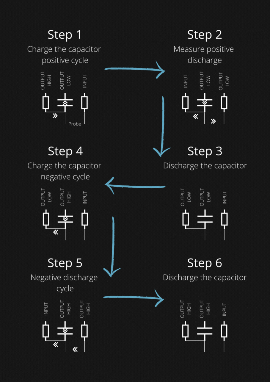
There are 6 steps in the code to read the EC value but also to reverse polarity to avoid probe corrosion.
The ESP32 changes the state of the 3 pins during the 6 steps here is what the code does.![]()
The EC is measured in step 2 here is the code:
    endCycle = 0;
    startTime = micros();
    pinMode (CP_PIN,INPUT);
    startCycle = ESP.getCycleCount();

    attachInterrupt(CP_PIN, isrCountEndCycle, FALLING);
    digitalWrite(EC_PIN, LOW);
    pinMode(EC_PIN, OUTPUT);
    while (endCycle == 0) {                   // endCyle gets set in the ISR, when an interrupt is received.
      if (micros() - startTime > EC_TIMEOUT) { // Time out - in case sensor not connected or not in water.
        timeout = true;
        break;
      }
    }
    detachInterrupt(CP_PIN);
    if (timeout) break;
    dischargeCycles = endCycle - startCycle;
    totalCycles += dischargeCycles;
The capacitor discharges into the two resistors, one of which passes through the probe. The ESP32 detects when the state of the CAPPOS pin changes from HIGH to LOW and triggers this function :
void IRAM_ATTR isrCountEndCycle() {
     endCycle = ESP.getCycleCount();
}
The number of CPU cycles of the ESP32 is calculated in order to have an accurate and reproducible discharge time.
Then we have to make solutions of different EC to calibrate the sensor.
Here is how we made an EC sensor for less than 5€.The EC sensor will be added to the next PCB to analyse water quality as foreseen in the UltraTower functional block diagram.
Here is the whole code adapted from this project:
#define CP_PIN 18 #define CN_PIN 19 #define EC_PIN 27 // Time constants in MICROSECOND ! #define CHARGEDELAY 36 // Time in microseconds it takes for the cap to charge; at least 5x RC. // 22 nF & 330R resistor RC = 7.25 us, times 5 = 36.3 us. #define DISCHARGEDELAY 14 // Discharge the cap before flipping polarity. Better for the pins. 2xRC. #define EC_TIMEOUT 2000 // Timeout for the EC measurement in microseconds. // 2 ms half cycle --> 250 Hz. uint32_t readECSensor() { uint32_t dischargeCycles = 0; // The number of clock cycles it took for the capacitor to discharge. uint32_t totalCycles = 0; // The cumulative number of clock cycles over all measurements. uint32_t startCycle; // The clock cycle count at which the measurement starts. uint32_t startTime; // The micros() count at which the measurement starts (for timeout). bool timeout = false; for (uint16_t i=0; i < (1 << oversamplingRate); i++) { // take 2^ECSAMPLES measurements of the EC. /////////////////////////////////////////////////////////////////////// // Stage 1: charge the cap, positive cycle. // CAPPOS: output, high. // CAPNEG: output, low. // EC: input. digitalWrite(CP_PIN, HIGH); digitalWrite(CN_PIN, LOW); pinMode (EC_PIN, INPUT); pinMode (CP_PIN, OUTPUT); pinMode (CN_PIN, OUTPUT); delayMicroseconds(CHARGEDELAY); // allow the cap to charge fully. /////////////////////////////////////////////////////////////////////// // Stage 2: measure positive discharge cycle by measuring the number of clock cycles it takes // for pin CAPPOS to change from HIGH to LOW. // CAPPOS: input. // CAPNEG: output, low (unchanged). // EC: output, low. endCycle = 0; startTime = micros(); pinMode (CP_PIN,INPUT); startCycle = ESP.getCycleCount(); attachInterrupt(CP_PIN, isrCountEndCycle, FALLING); digitalWrite(EC_PIN, LOW); pinMode(EC_PIN, OUTPUT); while (endCycle == 0) { // endCyle gets set in the ISR, when an interrupt is received. if (micros() - startTime > EC_TIMEOUT) { // Time out - in case sensor not connected or not in water. timeout = true; break; } } detachInterrupt(CP_PIN); if (timeout) break; dischargeCycles = endCycle - startCycle; totalCycles += dischargeCycles; /////////////////////////////////////////////////////////////////////// // Stage 3: fully discharge the cap, prepare for negative cycle. // Necessary to keep total voltage within the allowed range (without these discharge cycles the voltage would jump to about +1.4*Vcc and -0.4*Vcc) // CAPPOS: output, low. // CAPNEG: output, low (unchanged). // EC: input. digitalWrite(CP_PIN, LOW); digitalWrite(CN_PIN, LOW); pinMode (EC_PIN, INPUT); pinMode (CP_PIN, OUTPUT); pinMode (CN_PIN, OUTPUT); delayMicroseconds(DISCHARGEDELAY); /////////////////////////////////////////////////////////////////////// // Stage 4: charge the cap, negative cycle. // CAPPOS: output, low (unchanged). // CAPNEG: output, high. // EC: input (unchanged). digitalWrite (CN_PIN, HIGH); delayMicroseconds (CHARGEDELAY); /////////////////////////////////////////////////////////////////////// // Stage 5: negative discharge cycle, compensation. // CAPPOS: input. // CAPNEG: output, high (unchanged). // EC: output, high. digitalWrite (EC_PIN, HIGH); pinMode (CP_PIN,INPUT); pinMode (EC_PIN, OUTPUT); delayMicroseconds (dischargeCycles / 250); /////////////////////////////////////////////////////////////////////// // Stage 6: fully discharge the cap, prepare for positive cycle. // CAPPOS: output, high. // CAPNEG: ouput, high (unchanged). // EC: input. digitalWrite(CP_PIN, HIGH); pinMode(CP_PIN, OUTPUT); pinMode(EC_PIN, INPUT); delayMicroseconds(DISCHARGEDELAY); } if (timeout) { dischargeCycles = 0; } else { dischargeCycles = (totalCycles >> oversamplingRate); } // Disconnect the sensor. pinMode(CP_PIN, INPUT); pinMode(CN_PIN, INPUT); pinMode(EC_PIN, INPUT); return dischargeCycles; } -
Old and new PCBs
09/03/2022 at 14:37 • 0 commentsOld PCB
![]()
The first PCB had many problems:
- The IRFZ44N MOSFETs are not suitable for the AC current of the capacitor and coil. See this log.
- The coil can be optimized
- The capacitors are polarized. The risk is that they explode...
As a reminder, the ESP32 code alternates the operations of the disks to allow MOSFETs cooling.
This first PCB was perfect for testing but needed to be improved.
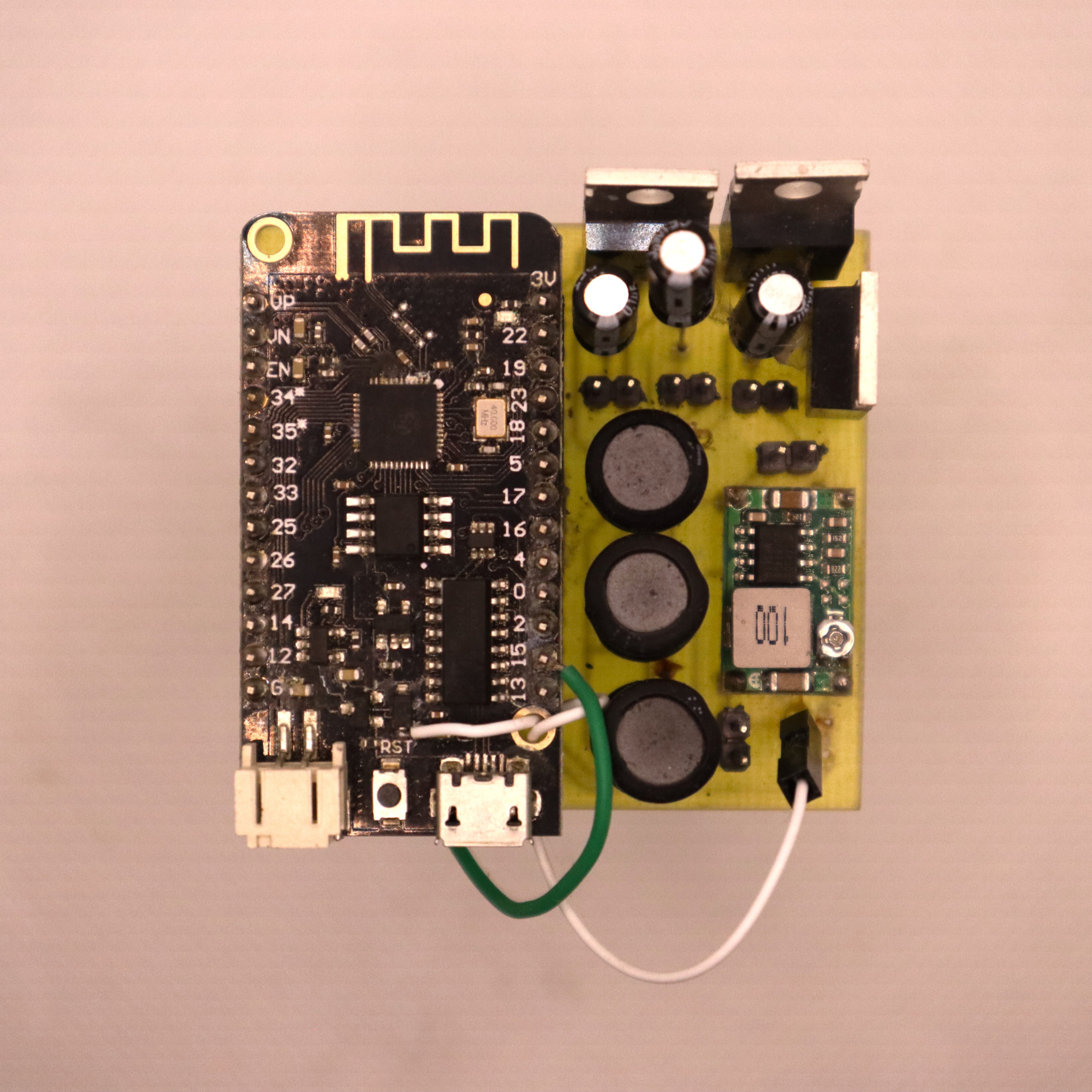
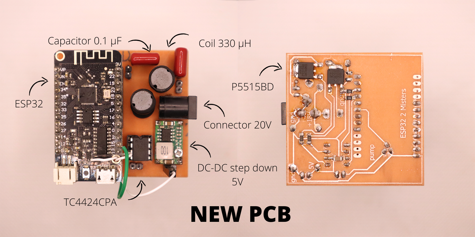
New PCB
![]()
The new PCB uses only 2 disks for redundancy, the third disk is removed as the new P5515BD MOSFETs no longer heat up and can theoretically run continuously.
The addition of the TC4424CPA MOSFET driver is necessary as the ESP32 fails to activate the MOSFETs with 3.3V.The use of a 330 µH coil and a 0.1µF capacitor allows to reach peaks at 77V allowing a good activation of the disks. The capacitor is a CBB 104J 400V 0.1µF, it is far too oversized and will have to be changed on future versions of the PCB.
The PCB is a single layer one for development, I'll do a double layers version when the circuit will be fully tested on a long term basis. I'll start these tests with the new tower on Monday.
The gerber files can be found here : gerber_PCB_V2Here is a video of the 2 misters new PCB in operation:
Schematics
![]()
-
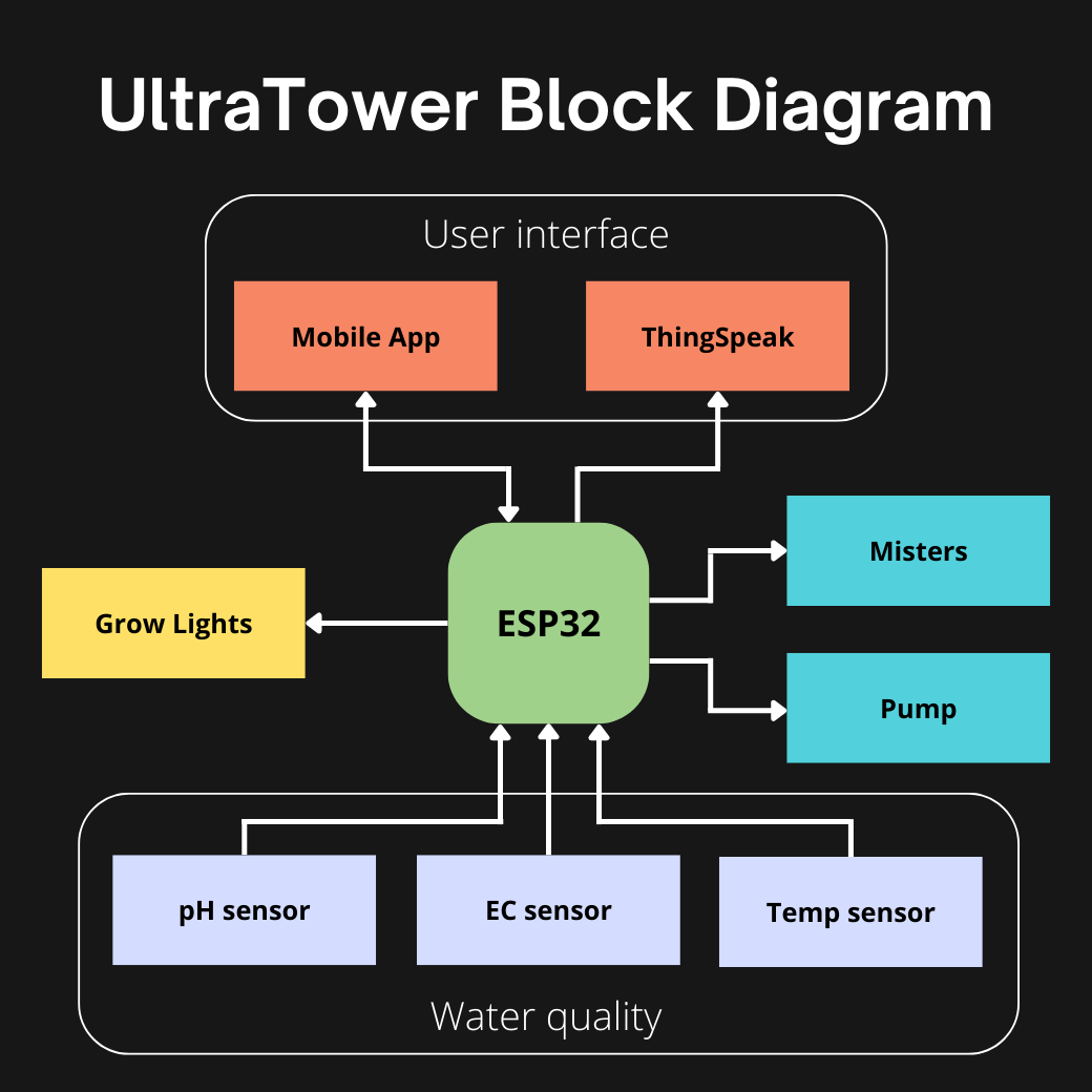
Functional block diagram
08/31/2022 at 18:21 • 2 comments![]()
Microcontroller:
The chosen microcontroller is an ESP32 because:
- The high frequency generation is simple
- Bluetooth and WiFi (to communicate with a phone or send data over the internet)
- Low power consumption
- Capacitive touch GPIO (water level sensors)
- Lots of pins for the many sensors
The ESP32 MCU is the heart of the system. It manages (or will manage) all the following functions.
Misters:
For the moment I am focusing on the optimisation of the most important block which is the misters. It is the activation of the disks at 108kHz that allows to create the fog composed of water and nutrients. As this log shows it's going pretty well.
Pump:
The pump is a finished block, it allows the water to flow back into the small tank when the water level is low. Because the disks should not work without water, it damages them.
Water quality:
These are the next blocks I need to work on. They consist of a pH sensor, an EC sensor and temperature sensors (in the main tank, root chamber and ambient temperature). The water quality is very important, for the plants to grow optimally.
User interface
Once the sensors are implemented, adding thinkspeak will be quite simple to see datas in real time. In the future, I'd like to make a Kotlin application to be able to receive data from the sensors but also to change the tower parameters (misters activation time, target pH, temperature alert, ...)
Light Grow
The addition of horticultural LEDs will allow plants to be grown anywhere, even in a cellar. But not necessary for sunny gardens or balconies.
A lot of work!!
-
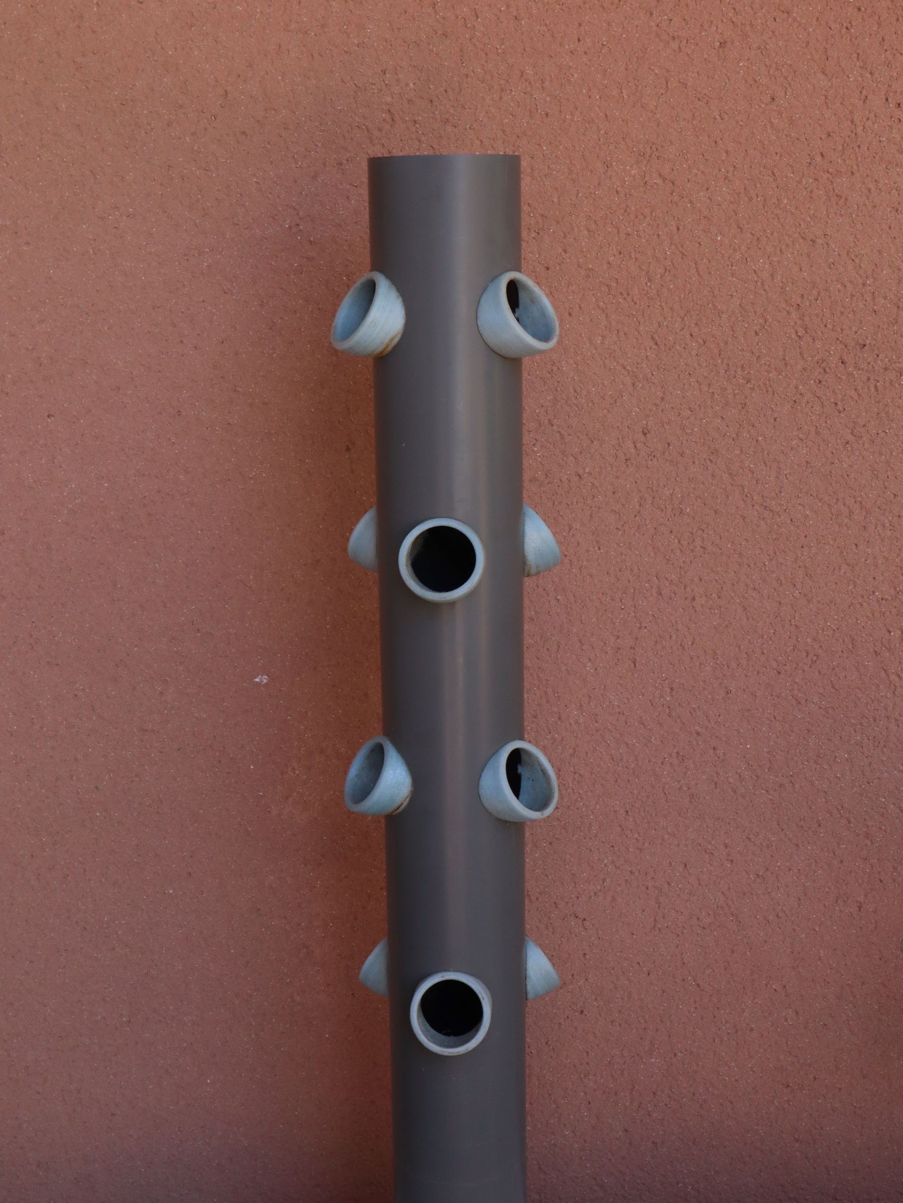
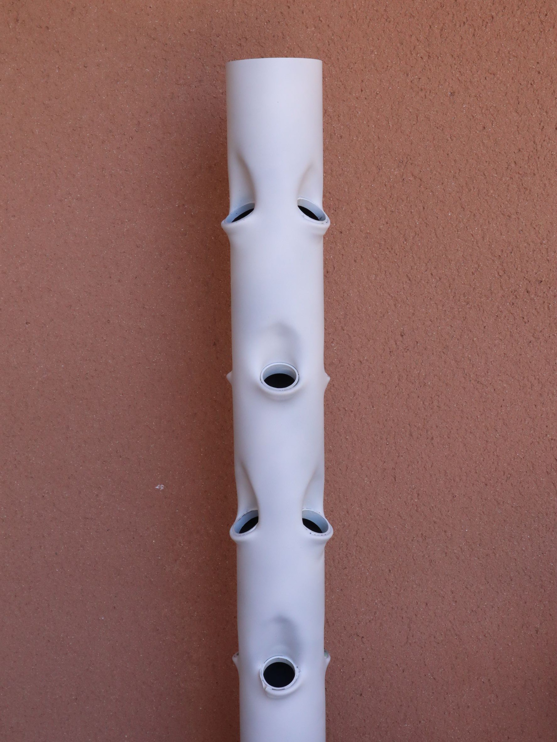
Improvement of tower PVC pipe
08/29/2022 at 16:28 • 2 commentsThe PVC pipe is an important part of this system. It is 100mm in diameter and 1 meter long, allowing 12 plants to be grown on a very small footprint.
Using the height allows us to optimise the number of feet per square meter.
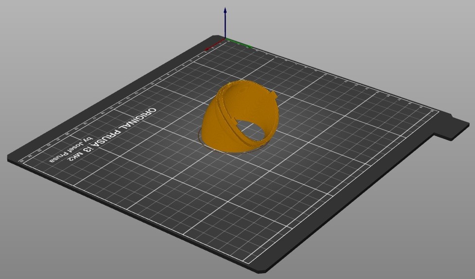
This PVC pipe is essential for this project however the current PVC design can be improved.Current design :
![]()
For each plant, this part must be printed.
![]()
It takes more than 1.5 hours of printing per piece, which makes 18 hours of printing for one tower. A lot of energy and plastic wasted.
Moreover this part gives a little too much horizontal angulation to the plants.New design
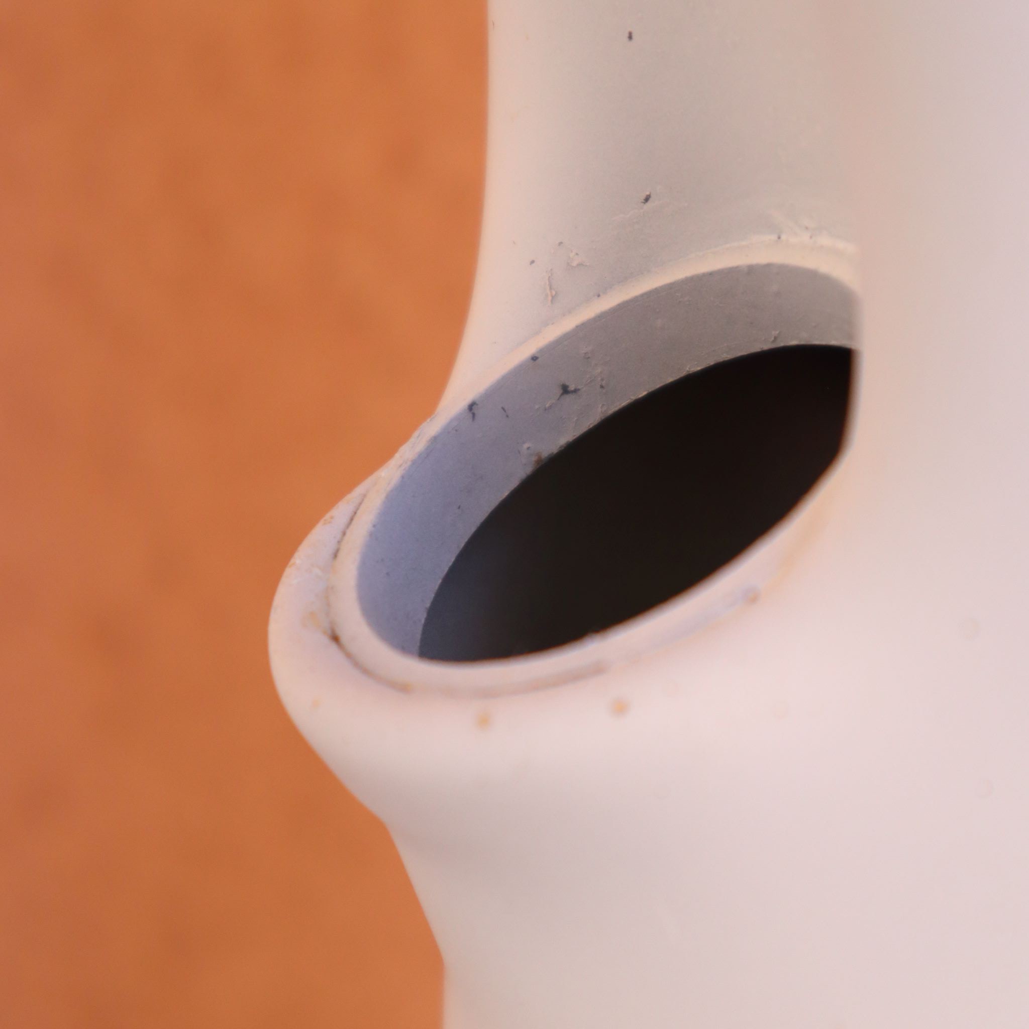
![]()
PVC can be heated to make it take a particular shape. The idea comes from this youtube video.
I thermoformed the large PVC tube with a small 40mm diameter PVC pipe which allows me to cut small 1cm long sections and glue them inside to make a small rim for the baskets.
![]()
When I have some time I'll make a video of how to do it.
I then painted the PVC white to reduce the heat inside the tube on sunny days.