Close
0%
0%

Canique Switch - nano power relay board

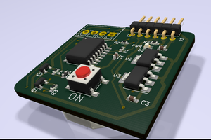
Canique Switch has a 60W latching relay onboard. The board consumes only 35nA when not switching.

Similar projects worth following
Typical relays consume constant power while they are "on". A smart socket e.g. will consume more power when the device connected to the socket is turned on.
Canique Switch is a relay board that consumes practically zero power whether on or off. It has a latching relay onboard which does not need any power to keep its current state. You can even completely disconnect power and the relay will still retain its current state.
The relay only consumes power when it changes state (from on to off or vice versa).

When using relays power is often wasted because a continuous current is flowing to keep the relay in "on" state.

A latching relay can overcome this issue. It retains its state without power.

Canique Switch typically consumes 35nA in sleep mode for the relay driver. But you can power it off completely and then it will consume zero power. The relay will still retain its state.

When you want to change state, which takes less than 10 milliseconds, the relay will typically consume 33 mA, assuming an input voltage of 3V. So that's approximately 100mW for max. 10ms.

This board is especially well suited for projects that do not constantly switch between on and off, but that keep state for a while.

There is one other advantage: The board provides a feedback pin that is an output pin. It tells you whether the relay is currently on or off. You can detect any switching failure by reading the feedback pin. You can also use the feedback pin to reduce switching time.
The feedback pin will only work while the board is powered via the 3V pin. You can disconnect power and reconnect it again - the feedback pin will tell the correct state as soon as 3V/GND is connected.

Usage

The board has 3 pins for controlling the relay: SET, RESET and ZZ (sleep). All are tied to GND by pull-down resistors. To switch state ZZ must be set high. Then you need to put SET to high and RESET to low or vice versa to turn the relay on/off.

Going back to sleep is achieved by putting all 3 input pins to LOW or by releasing them (high impedance). Then the internall pull-down resistors will do the work for you.

Quick Facts

  • Relay min VCC: 2.25V
  • Relay max VCC: 3.15V
  • Relay nominal VCC: 3V
  • Relay coil resistance: 90 Ohm ± 10%
  • Relay driving pulse time: 10ms
  • Relay contact ratings:
    Maximum Switching Power 60 W, 125 VA
    Maximum Switching Voltage 220 VDC, 250 VAC
    Maximum Switching Current 2 A
    Maximum Carrying Current 2 A

Roadmap

A future version (HW rev 0.3) will omit the sleep pin altogether and use an auto-sleep circuitry.

  • Auto-sleep in HW rev 0.3

    canique04/16/2023 at 12:38 0 comments

    In HW revision 0.3 the sleep pin is without function.

    Instead there is an auto-sleep circuit onboard, that will make the board sleep when not actively driving SET or RST high.

    To switch the relay on, it is enough to only drive the SET pin high for 10ms (while RST is in high impedance or driven low).

    To switch the relay off, it is enough to only drive the RST pin high for 10ms (while SET is in high impedance or driven low).

View project log

  • 1
    Connect wires to board

    To use Canique Switch, you need to connect at minimum:

    VCC - connect to a power supply 2.25-3.15V
    GND - connect to GND of power supply
    SET - connect to a microcontroller or drive manually
    RST - connect to a microcontroller or drive manually
    ZZ - connect to a microcontroller or drive manually

    (SET/RST/ZZ are relative to GND.)

    AC Load

    For an AC load that you want to switch on/off, you need to connect:

    L (Live) - connect this to the live (L) wire of your AC supply
    NO (Normally open) / NC (Normally closed) - connect one of them to your load. The NO/NC output is either internally disconnected or internally connected to the wire that you attached to L depending on the relay state. NO means if the relay is off, NO has no connection to L, and gets connected to L as soon as the relay switches on. NC is the exact opposite of NO.

    For examply, usually you'd connect a LED light bulb to NO.

    Connect the N (Neutral) wire of your load directly to the N wire of your AC supply.

    DC Load

    For a DC load that you want to switch, you need to connect:

    L (Live) - connect this to the VCC of your DC power supply (max 220V DC)
    NO (Normally open) / NC (Normally closed) - connect one of them to the positive input of your load.

    Connect the GND of your load directly to the GND of your DC power supply.

  • 2
    Turn relay on
    1. Drive ZZ high (to volage of VCC, e.g. 3V)
    2. Drive SET high, drive RST low
    3. Wait for ~10ms
    4. Drive ZZ, SET, RST low or disconnect them (high impedance).
    5. If you want you can also disconnect VCC/GND. The relay will keep its turned on state.
  • 3
    Turn relay off
    1. Drive ZZ high (to volage of VCC, e.g. 3V)
    2. Drive RST high, drive SET low
    3. Wait for ~10ms
    4. Drive ZZ, SET, RST low or disconnect them (high impedance).
    5. If you want you can also disconnect VCC/GND. The relay will keep its turned off state.

View all 3 instructions

Enjoy this project?

Share

Discussions

Similar Projects

Does this project spark your interest?

Become a member to follow this project and never miss any updates