What is a Light Dependent Resistor (LDR) or Photoresistor?
A Light Dependent Resistor (also known as a photoresistor or LDR) is a device whose resistivity is a function of the incident electromagnetic radiation. Hence, they are light-sensitive devices. They are also called photoconductors, photoconductive cells, or simply photocells.
They are made up of semiconductor materials that have high resistance. There are many different symbols used to indicate a photoresistor or LDR, one of the most commonly used symbols is shown in the figure below. The arrow indicates light falling on it.
")

555 Timer IC
555 timer is one of the most used IC in electronics, especially for triggering purposes. Whether a simple project involving a single 8-bit microcontroller and some peripherals or a complex one involving a system on chips (SoCs), 555 timer working is concerned. Depending on the manufacturer, the standard 555 timer package includes 25 transistors, two diodes, and 15 resistors on a silicon chip installed in an 8-pin mini dual-in-line package (DIP-8). Variants consist of combining multiple chips on one board. However, 555 is still the most popular.


A 555 timer working as a flip flop or multi-vibrator has a particular set of configurations.
Pin 1. Ground: This Pin should be connected to the ground.
Pin 2. TRIGGER: Trigger pin is dragged from the negative input of comparator two. The Lower comparator output is connected to the SET pin of the flip-flop. A negative pulse (< Vcc/3) on this Pin sets the Flip flop, and the output goes High.
Pin 3. OUTPUT: This Pin also has no particular function. This is the output pin where the Load is connected. It can be used as a source or sink and drive up to 200mA current.
Pin 4. Reset: There is a flip-flop in the timer chip. The reset pin is directly connected to the flip-flops (Master Reset). This active Low Pin is typically connected to VCC to prevent accidental Reset.
Pin 5. Control Pin: The control pin is connected to the negative input pin of comparator one. Output Pulse width can be controlled by applying a voltage at this Pin, irrespective of the RC network. Typically this Pin is pulled down with a capacitor (0.01uF) to avoid unwanted noise interference with the working.
Pin 6. THRESHOLD: Threshold pin voltage determines when to reset the flip-flop in the timer. The threshold pin is drawn from the positive input of the upper comparator. If the control pin is open, a voltage equal to or greater than VCC*(2/3) will reset the flip-flop. So the output goes low.
Pin 7. DISCHARGE: This Pin is drawn from the open collector of the transistor. Since the transistor (on which discharge pin got taken, Q1) got its base connected to Qbar. Whenever the output goes low, or the flip-flop gets reset, the discharge pin is pulled to the ground, and the capacitor discharges.
Pin 8. Power or VCC: It is connected to a positive voltage (+3.6v to +15v).
Seeed Fusion PCB Assembly(the words " PCB Assembly " add with website link: https://www.seeedstudio.com/fusion_pcb.html) Service offers one-stop prototyping for PCB manufacture, PCB assembly and as a result, they produce superior quality PCBs and Fast Turnkey PCBA from 7 working days. When you prototype with Seeed Fusion, they can definitely provide Free DFA and Free functional tests for you! Check out their website to know about their manufacturing capabilities and service.Link to Seeed Fusion Service within the sentence: https://www.seeedstudio.com/pcb-assembly.html
Circuit Diagram
The complete circuit diagram for Automatic Fence Lighting with Alarm is shown above. LDR is placed facing toward the entrance, and a potentiometer is used to adjust the device's sensitivity. You can also switch between the negative Pin of the battery and LDR's grounded Pin to manually control this security system.

Working
Here, the op-amp IC...
Read more »
 Electroniclovers123
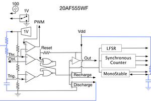
 Adrian Freed
 Shranav Palakurthi