 Yakroo108
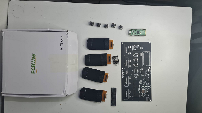
STEP 1 :
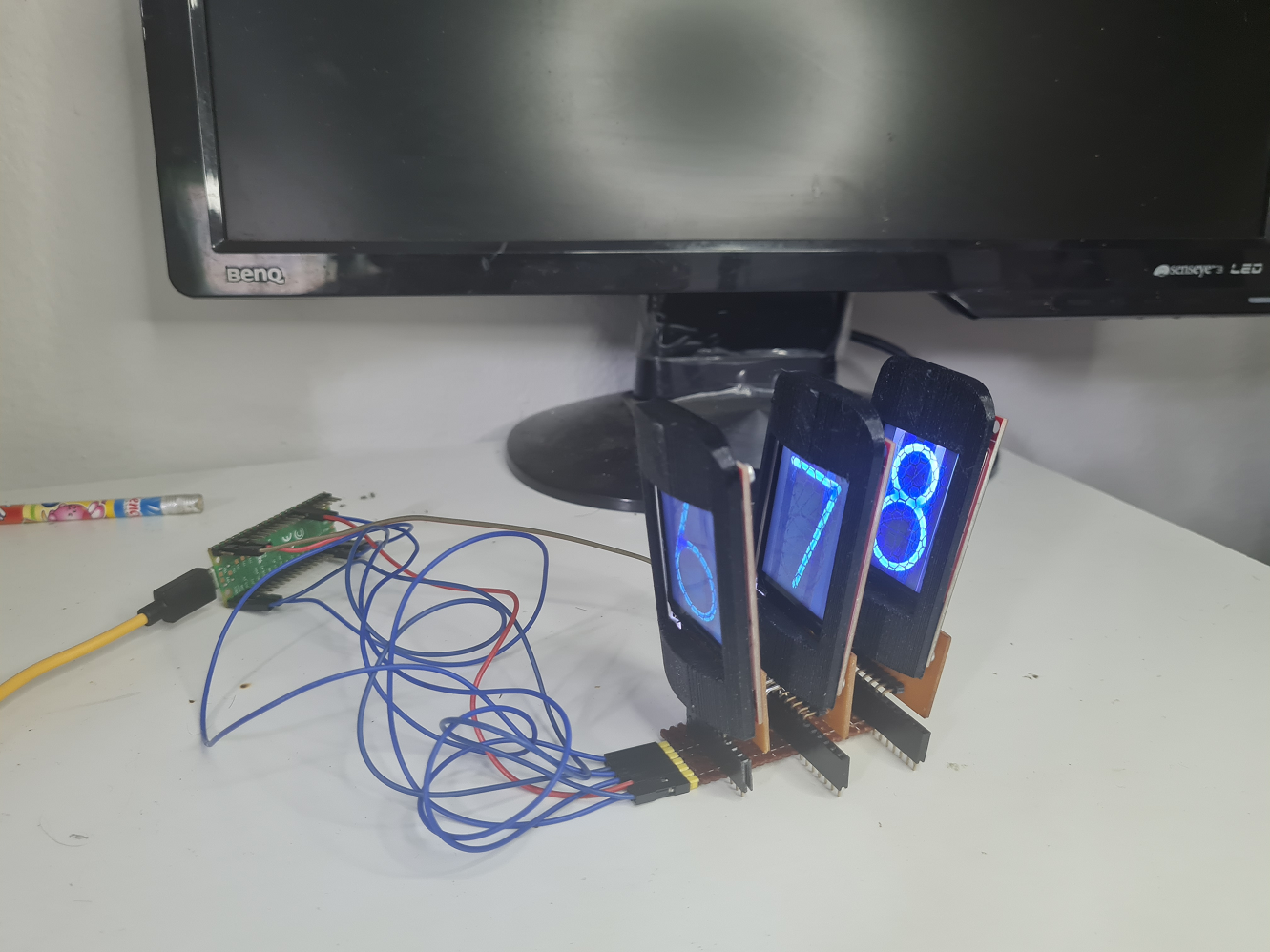
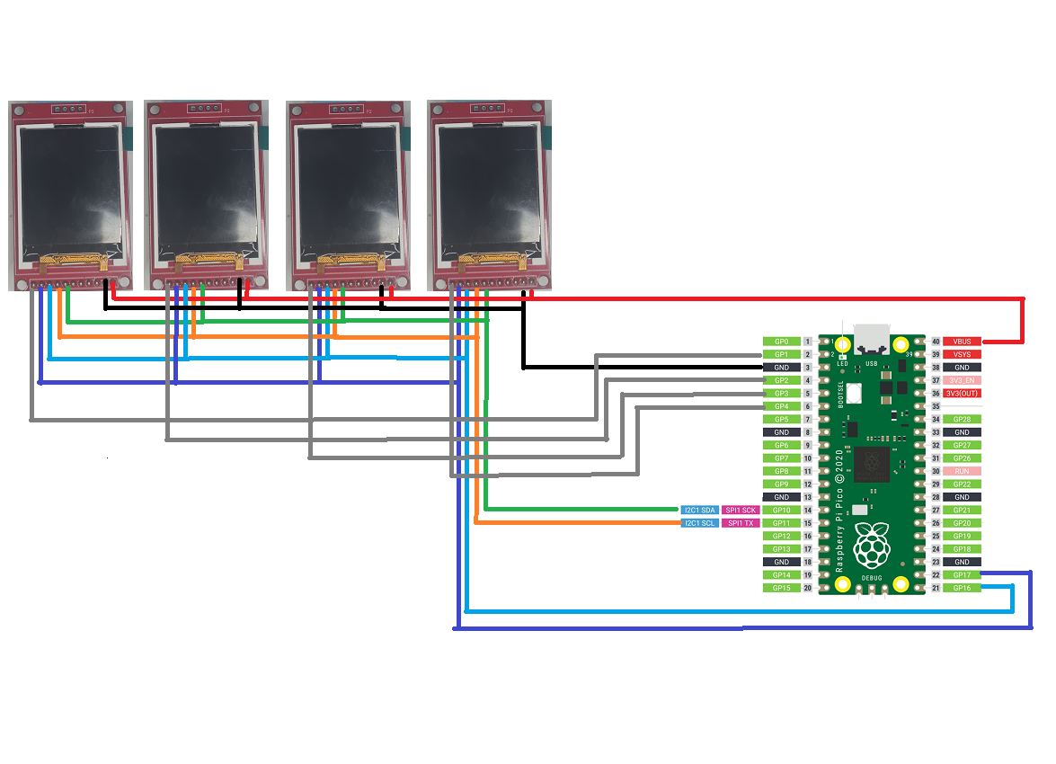
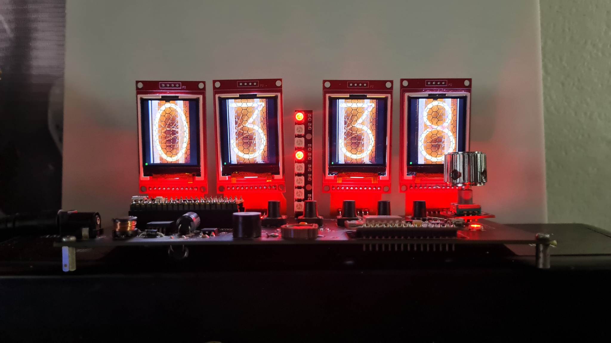
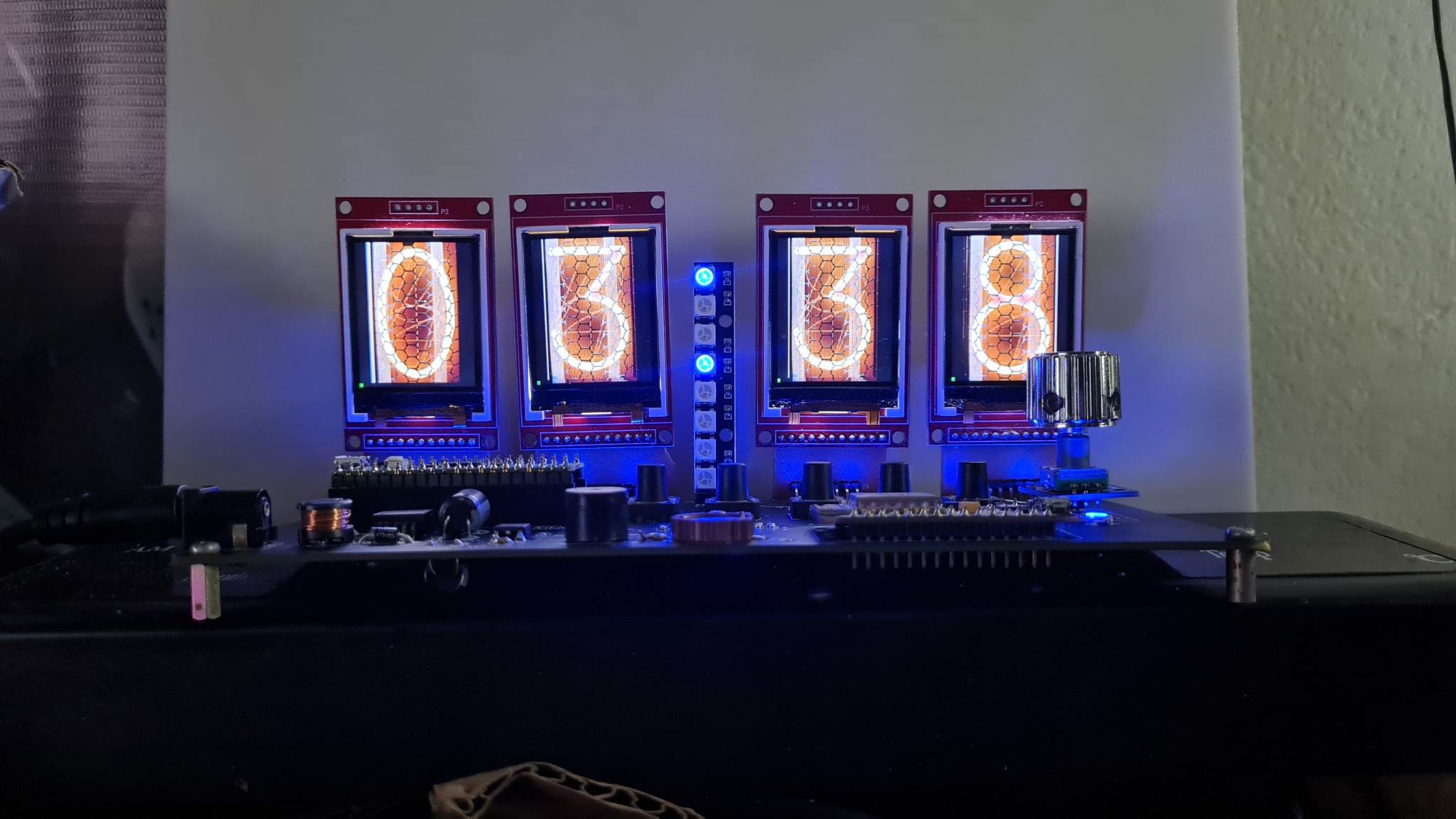
wring Raspbery PICO + ST7735
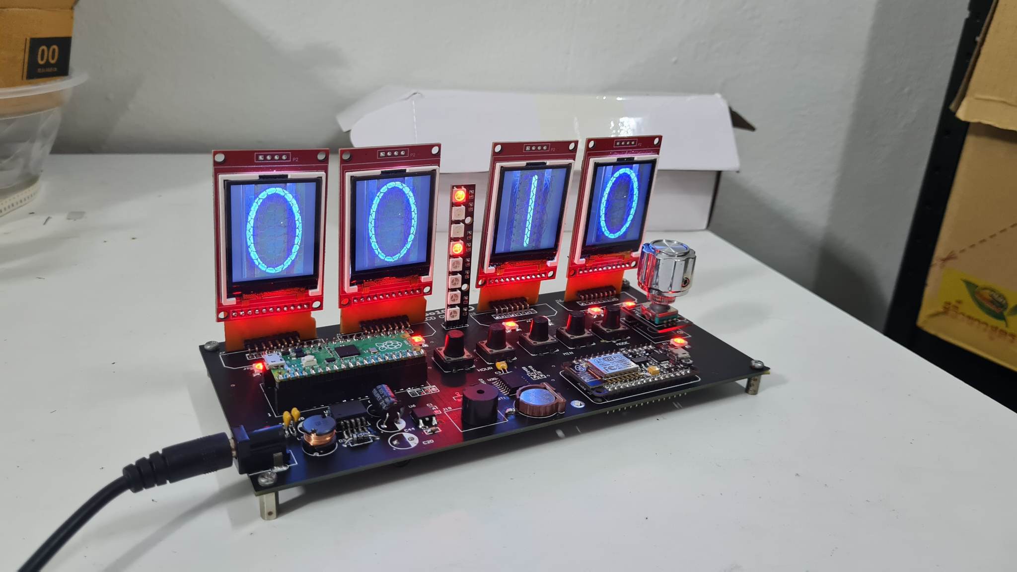
-test Load Bitmap Nixie clock BMP
STEP 2 :
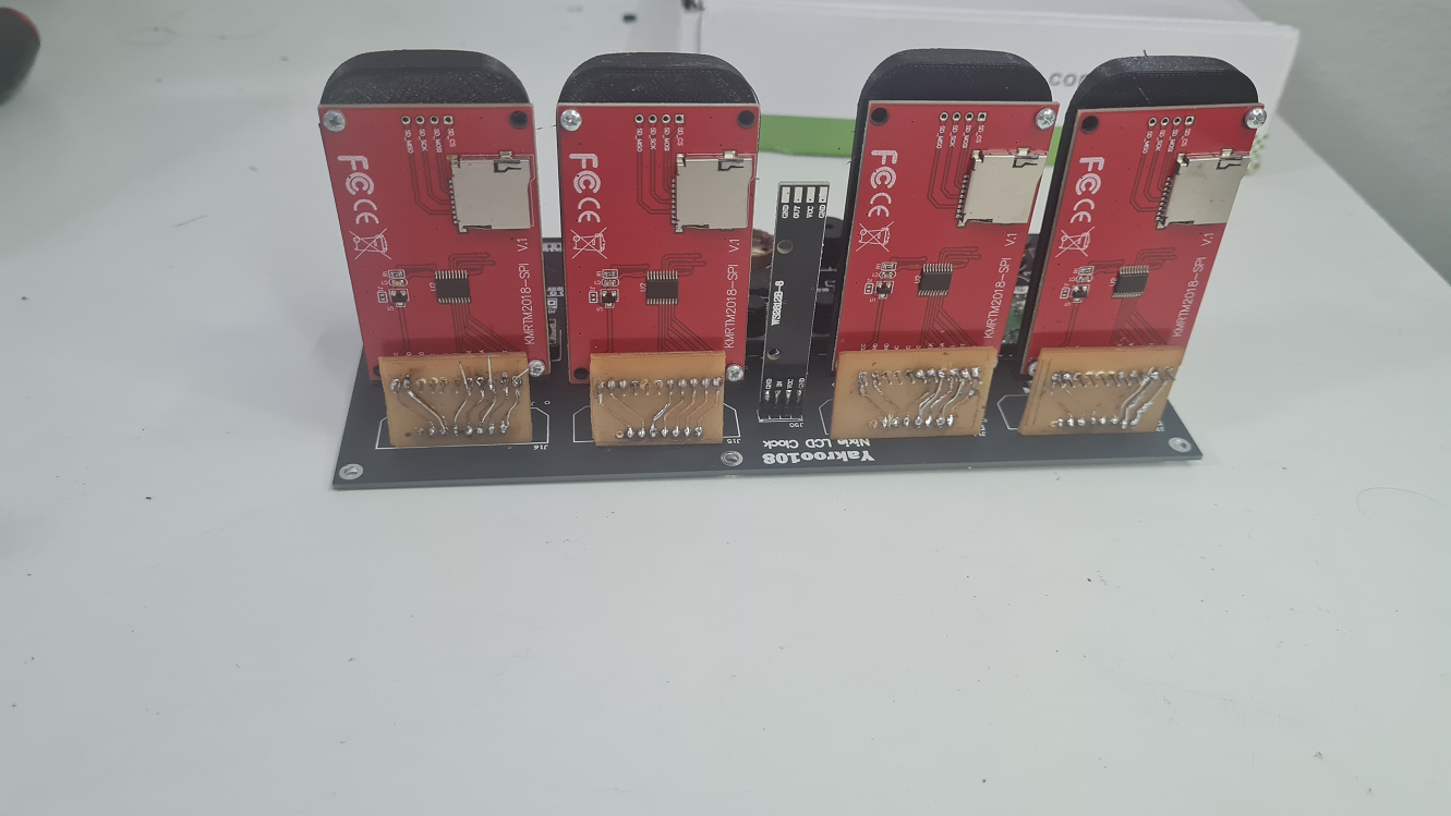
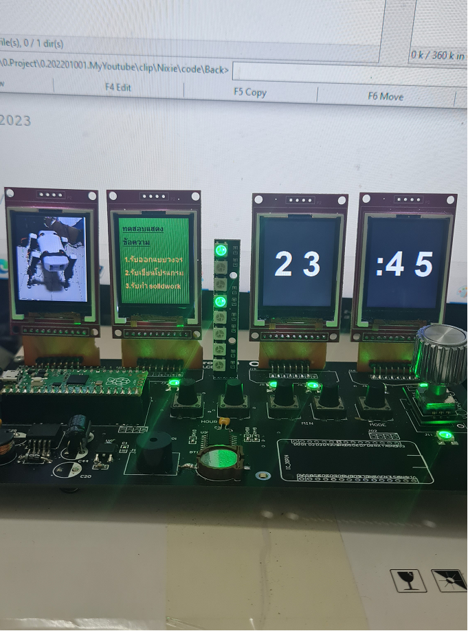
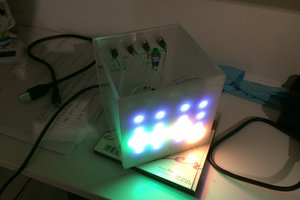
write Program for 4 LCD
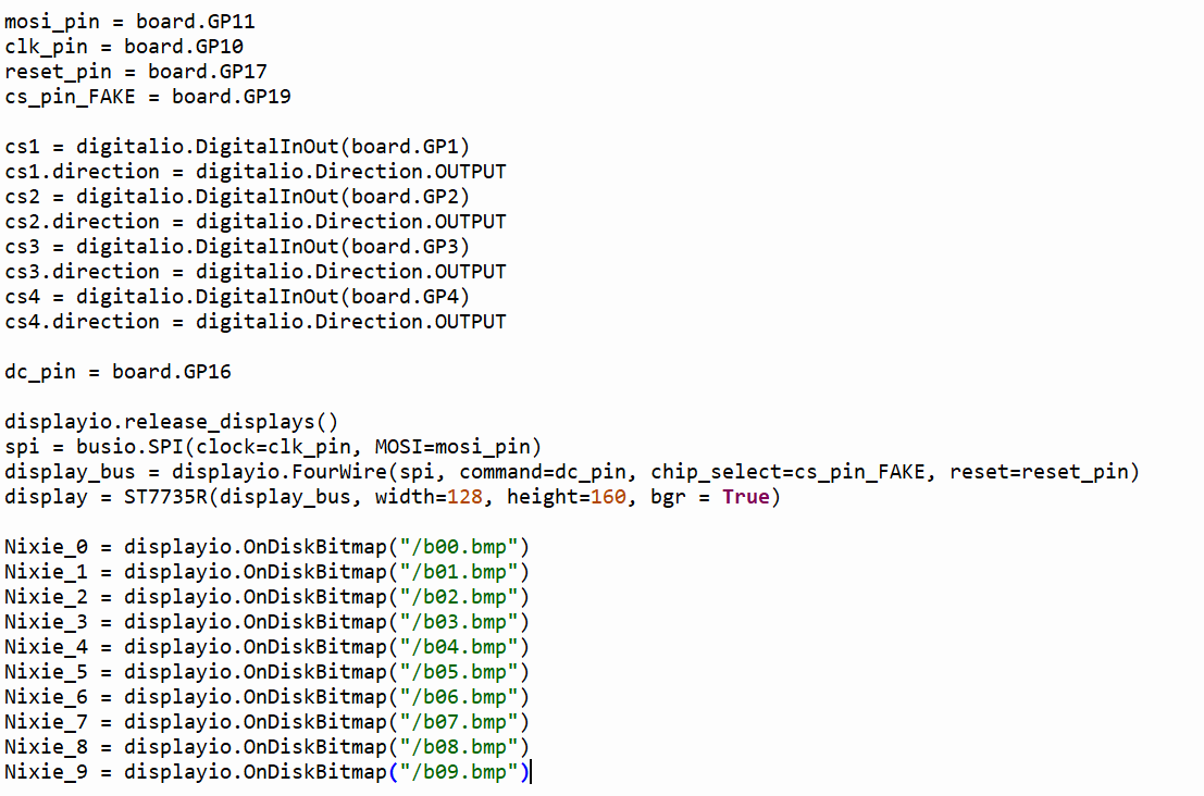
CODE: code+image file
https://github.com/YakrooThai/Nixie_Lcd_Clock
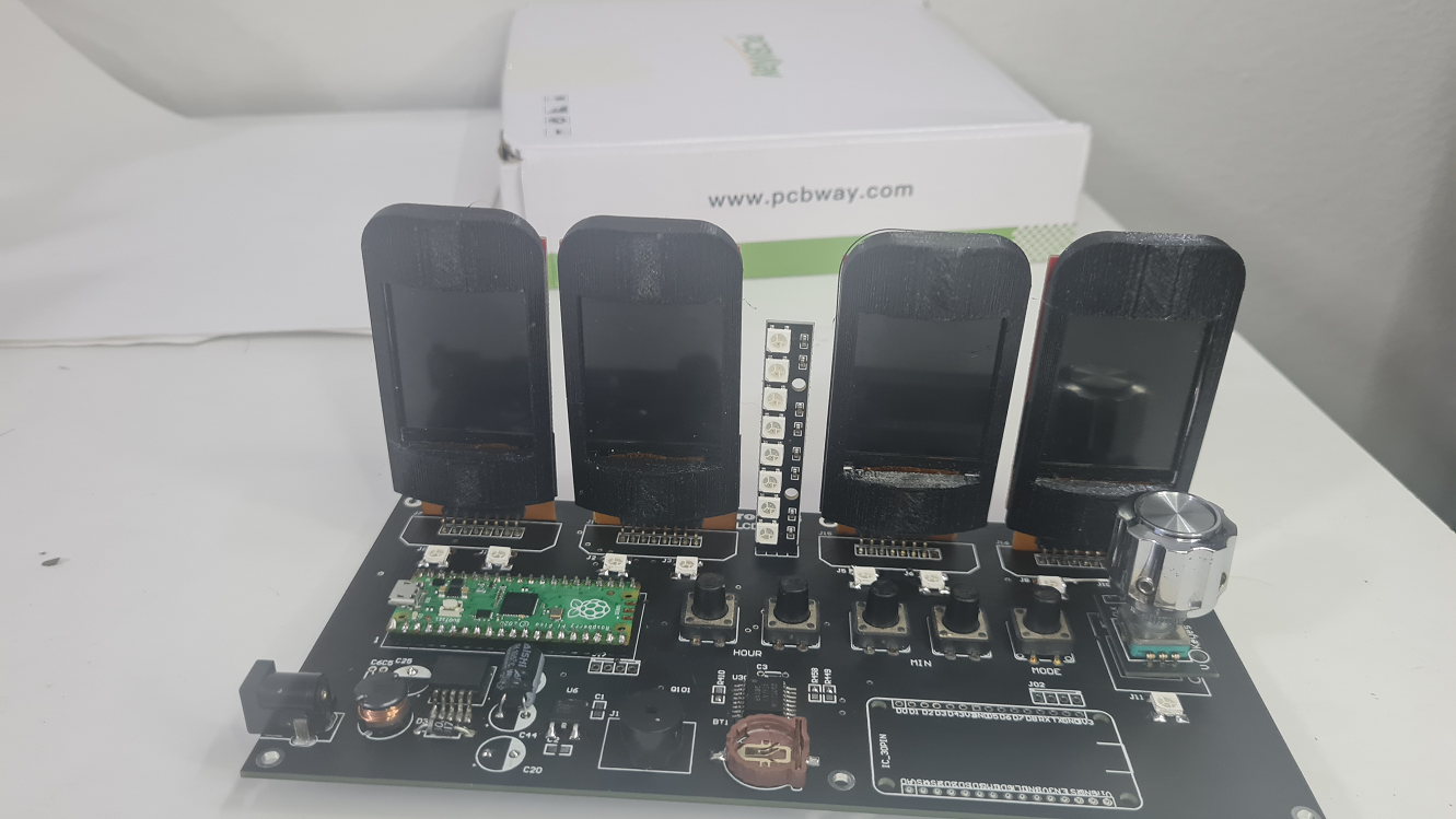
Step 3:
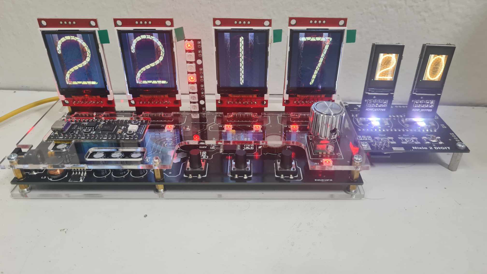
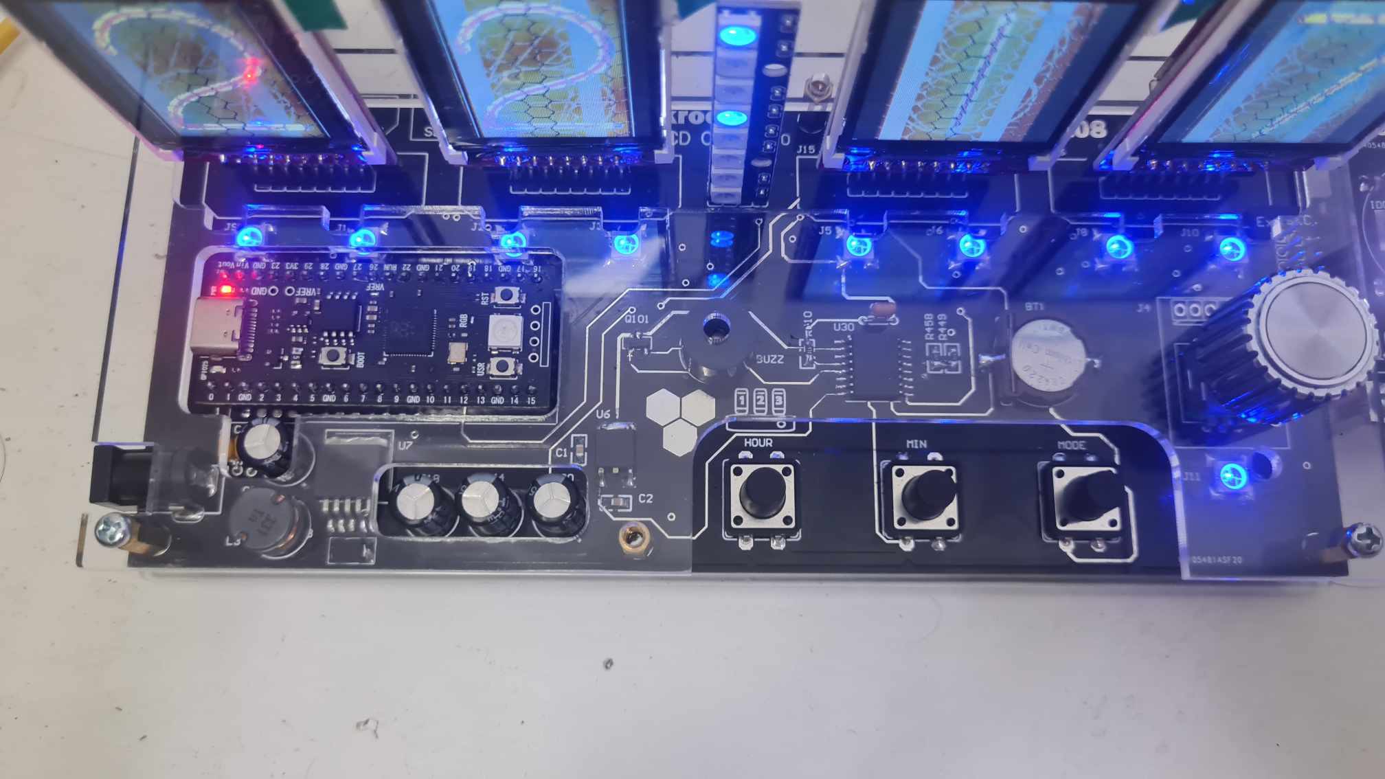
Connect Ds3231 RTC and PCB all in My Project
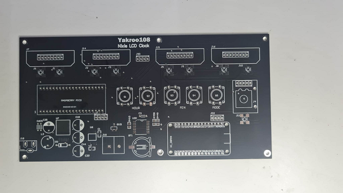
PCBWAY:
I would like to thank PCB-way for helping me to complete this project. Quality PCB made quickly, good price, fast delivery.
The PCB came out much more beautiful than I imagined. I'm very impressed with it.
Step5: Case Acrylic
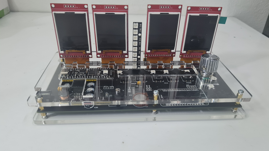
Update PCB v2.0
Order PCB:
https://www.pcbway.com/project/shareproject/Raspberry_PICO_Nixie_Clock_Lcd_f3d1c4a8.html?upId=0
You can contact
E-mail: mhooyang@gmail.com
Please follow my YouTube channel. Still a newbie to make a YouTube channel.
Just press Subscribe my youtube channel. Thankyou
https://www.youtube.com/@Yakroo108 < ===== ( -/|\-)

 Bharat Ramanathan
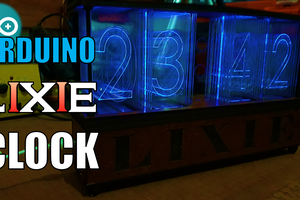
 DIY GUY Chris
 Marcel Ochsendorf
Maybe you can have a look here. Driver and pieces of code at your diposal.
https://hackaday.io/project/180211-faux-nixie-clock