 Jan Neumann
Why would I need something like this?
WiFi signals are invisible to humans. But they look pretty cool, as you can see in this v1.0 WiFi cam: https://hackaday.com/2021/11/22/visualizing-wifi-with-a-converted-3d-printer/
The obvious next step is to build something that is more practical to use and has more of an application than just taking one frame in one hour.
After I took the 3D measurements with this setup, I had in mind to build a navigation system that detects the phase of the standing wave in 3D to find out a (relative) position.
Also, I thought about trying to figure out, if this could be used as a passive radar to detect human movement just by watching the radio shadow/deformation they cause.
These ideas could only be tried and only make sense with real-time data.
So this is the reason to build it.
Code, documentation and hardware are also on GitHub:
https://github.com/Neumi/wifi_camera

How it works
Measuring RSSI values in many (known) locations from one (or multiple) networks to detect how the signal moves through space.
The first version had only one RSSI probe that was moved in 3D space and later processed to a 3D visualization.
This version should be able to process one whole 8x8 pixel slice in real time. To do so, I built a PCB where 16 ESP8266 are mounted in a grid pattern and connected to a shared i2c bus, a 'shutter' wire, and power. Four of these modules should be built to take 64 pix images.
The distance between the ESP modules is currently 26mm. This is enough to capture the standing wave at 2,4Ghz with a wavelength of 12,5cm. If we need more resolution, there is the option to take multiple frames from different locations (on the same plane).


The animation above shows the result of a scan with a distance of 1cm between slices and the pixels. You can clearly see high and low spots in the image. As the high and low spots are similar in both slices, we can be certain that these are not randomly appearing but show a repeatable result and a change of the 3D high and low spots thought the whole scan. Noise is still a problem though.
The 3D capturing rig is a modified 3D printer frame, where each axis is equipped with an Ethersweep controller: https://hackaday.io/project/187187-ethersweep
Technical implementation
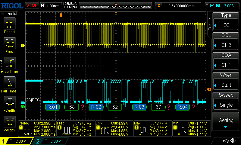
As said, ESP8266 modules are the core of this project and take the RSSI measurements. An i2c bus connects all ESPs to a master that collects all RSSI values and sends the further to a visualization pipeline.
The biggest challenge so far was the i2c bus debugging and the fragile power supply. It took some time to discover that ESP8266s do not support i2c slave mode natively and have issues at high clock speeds. 10KHz works for 1/4 of the 64 pix goal now and seems to be reliable.
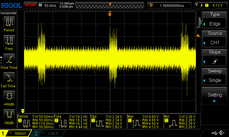
The power supply situation is challenging too. The test setup of 15 ESP modules consumes 1,1A at 3,3V. ESP8266 modules are known for being picky about a clean power supply. Some capacitors should do the trick for the larger version. Starting all nodes at once needs several tries. Most of the tries they, most likely, brown out at startup and fail to boot.
Next steps
I'm currently waiting on the missing 48 ESP8266 modules to arrive. While they are on their way, I'm working on a visualization that works in real-time.
Also, I'm thinking about a good solution for an interface to the sensor grid.
One option would be to directly connect a raspberry pi or similar to the i2c bus...
Read more »
 pastcompute
 Atheros

 electrobob