Kites for Future in action:
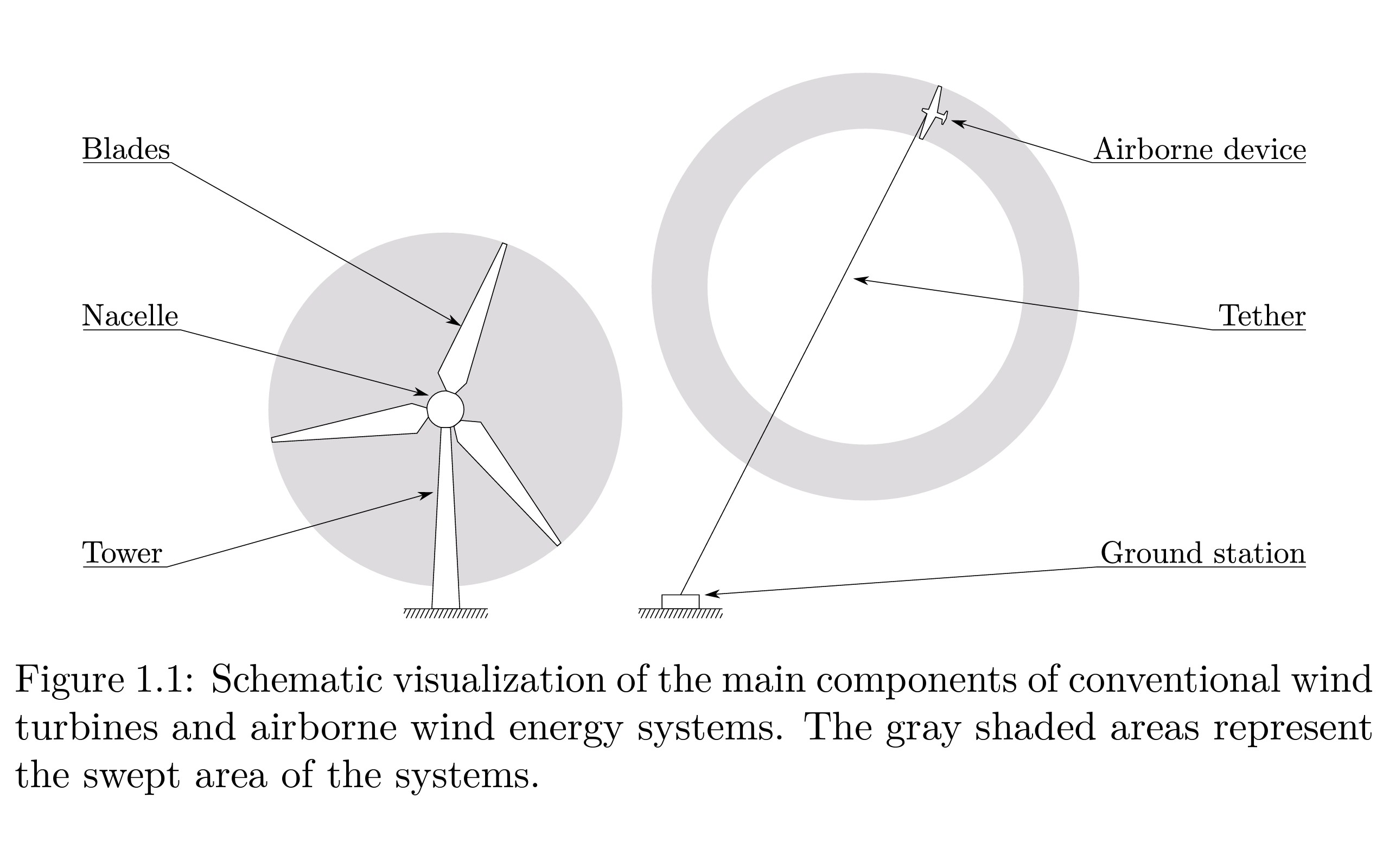
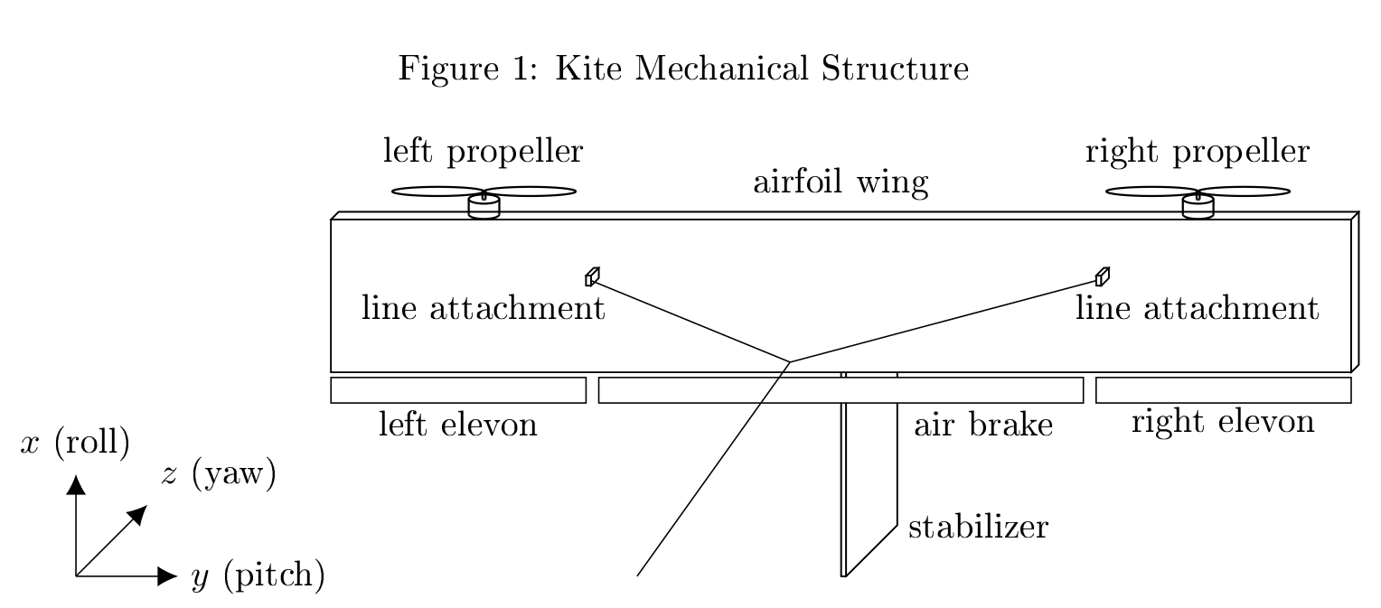
From Thomas Haas' Phd thesis we borrow the following picture:
Many projects around the world have tried to implement an autonomous airborne wind turbine and have proven in recent years that it works great.
For an overview of airborne wind energy systems, see:
Kitemill in Norway share their power production measurements, which look quite amazing:
However so far, none of these projects have an online shop selling the system. Except for https://kitewinder.fr/ but their system does not launch and land autonomously and sweeps a rather small area. So we had to make our own.
Our design goals, partly going well ahead of many of the existing projects, were:
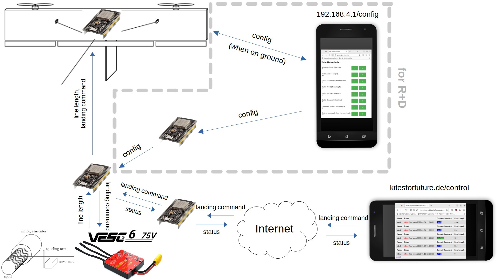
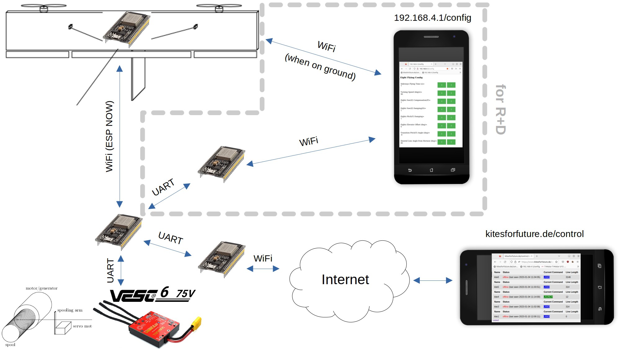
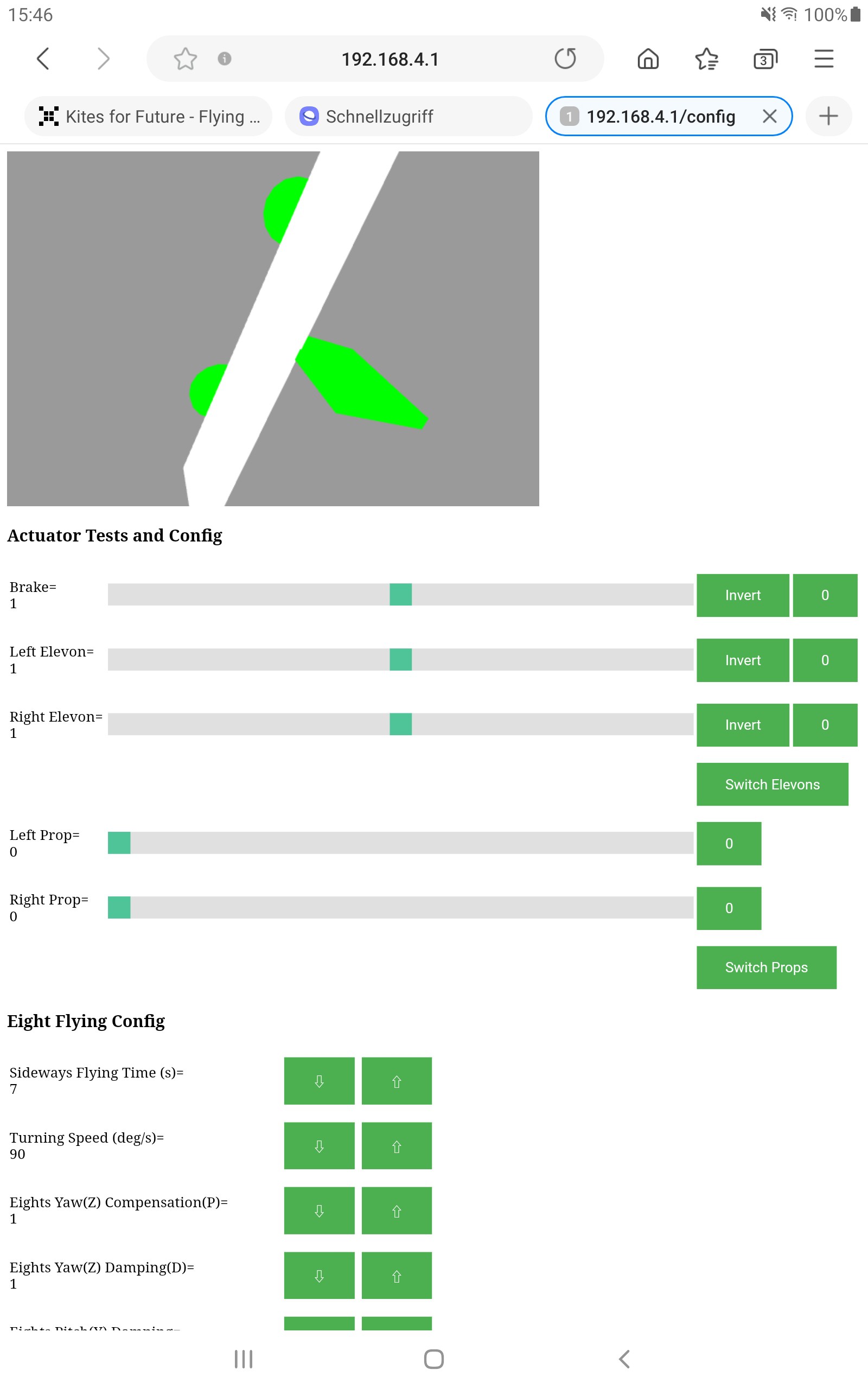
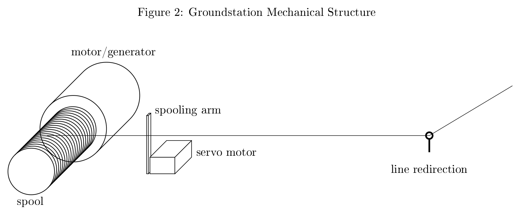
- As simple as possible, i.e. if possible no GPS, only one tether, ground station and kite communication kept to an absolute minimum, as few control surfaces and propellers as possible
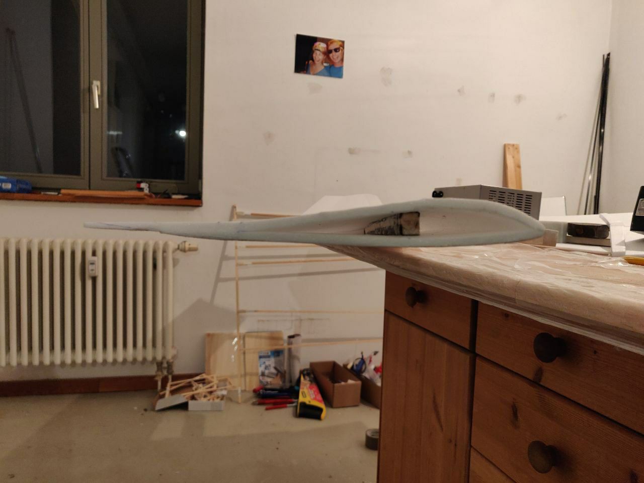
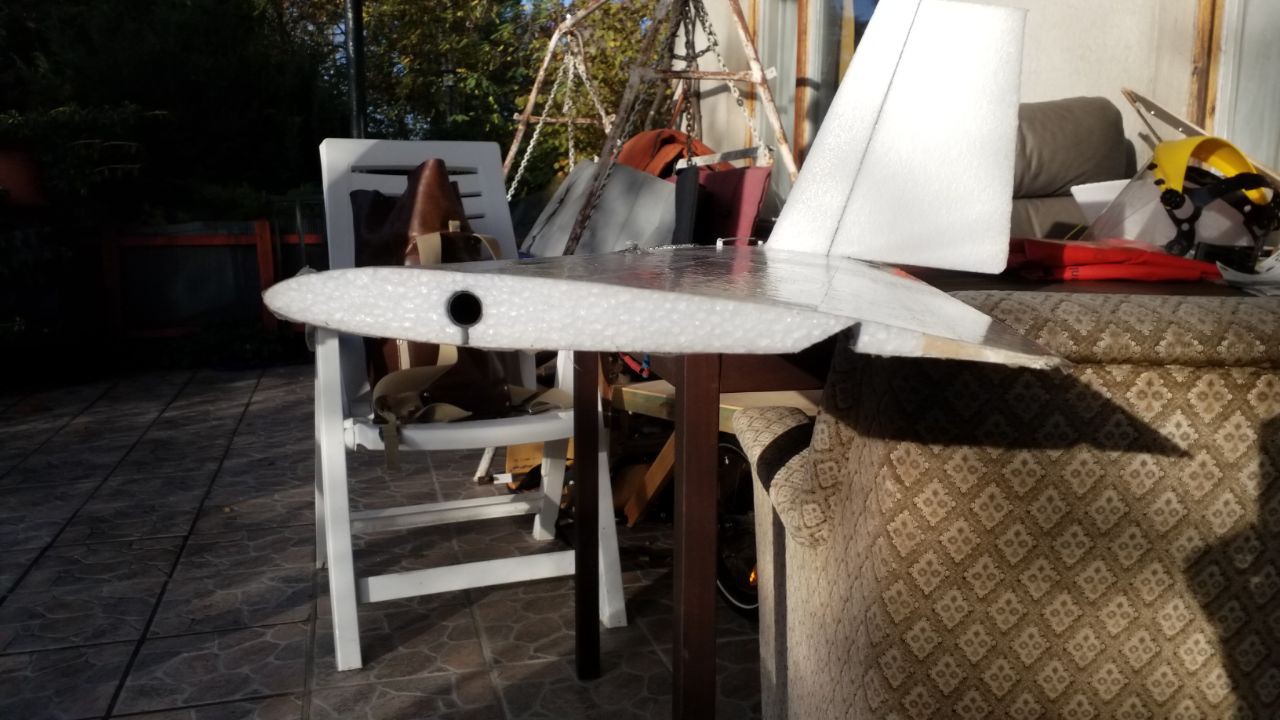
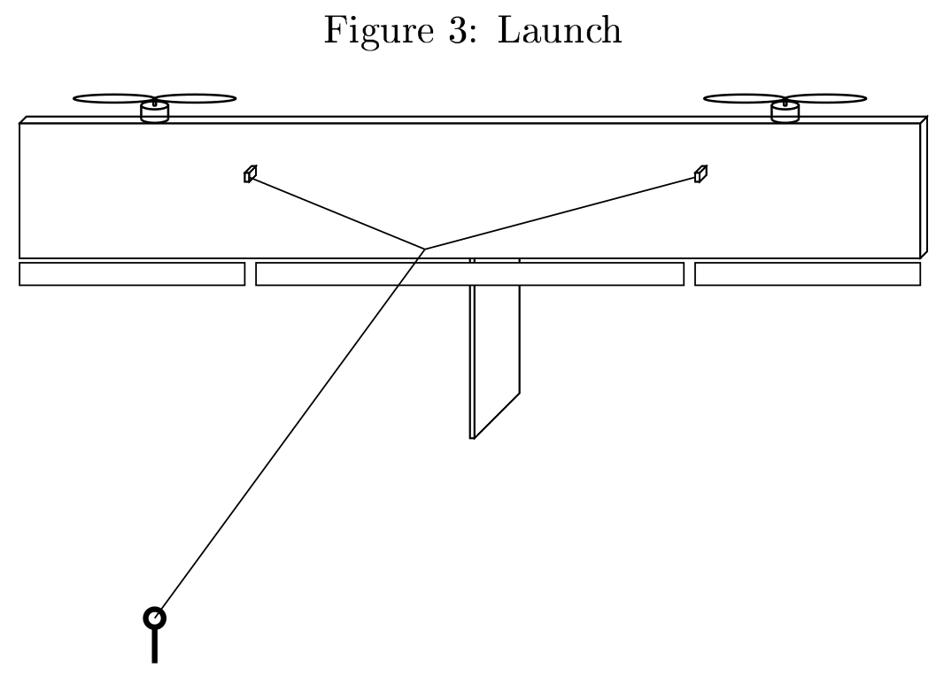
- Easy to transport, i.e. flying wing if possible
- Fully autonomous to enable service-free operation for months
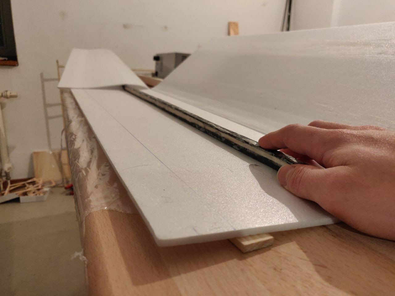
- Easy and cheap to manufacture at scale, using readily available parts
- Efficient and profitable even at very small scale (2m wingspan)
Advantages of our design that we discovered during testing:
- Scalable to very large size due to the possibility to have many tether attachment points along the wing spar that join at a common knot to the single tether going to the ground station
- Really fast precision landing as a glider not needing the propellers
- Really fast launch straight up (10 seconds)
- Can use conventional folding propellers
- Can use a wing without dihedral
- Can turn with either rudder or ailerons.
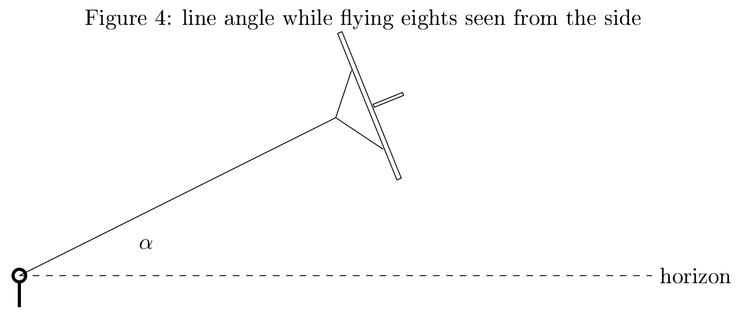
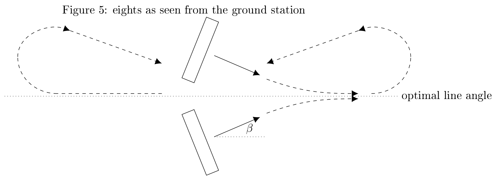
- Figure Eight autopilot extremely simple
- No wind sensors neccessary


 RichardCollins
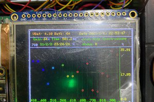
 Vijay
Vijay
Could you pair kites on the ends of a single cable, so that one kite could extend while the other retracts, and the power output could be (nearly) continuous?