 DIY GUY Chris
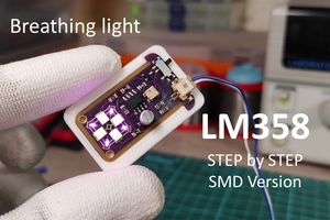
Maybe you saw this circuit elsewhere but certainly you never saw it in such customized design, this is an absolute DIY project that you can follow to produce your own Breathing light circuit based on the LM358 Operational amplifier and I'm putting the full details in the following instructions.
If you hate reading then maybe the above video will help you.
What you will learn here:
- Set the circuit by picking up the appropriate components.
- draw the circuit schematic and its related PCB design.
- Design a customized housing for your device.
- Bring the hardware and perform the assembly.
- Test your produced device and rock the vibes.
Supplies
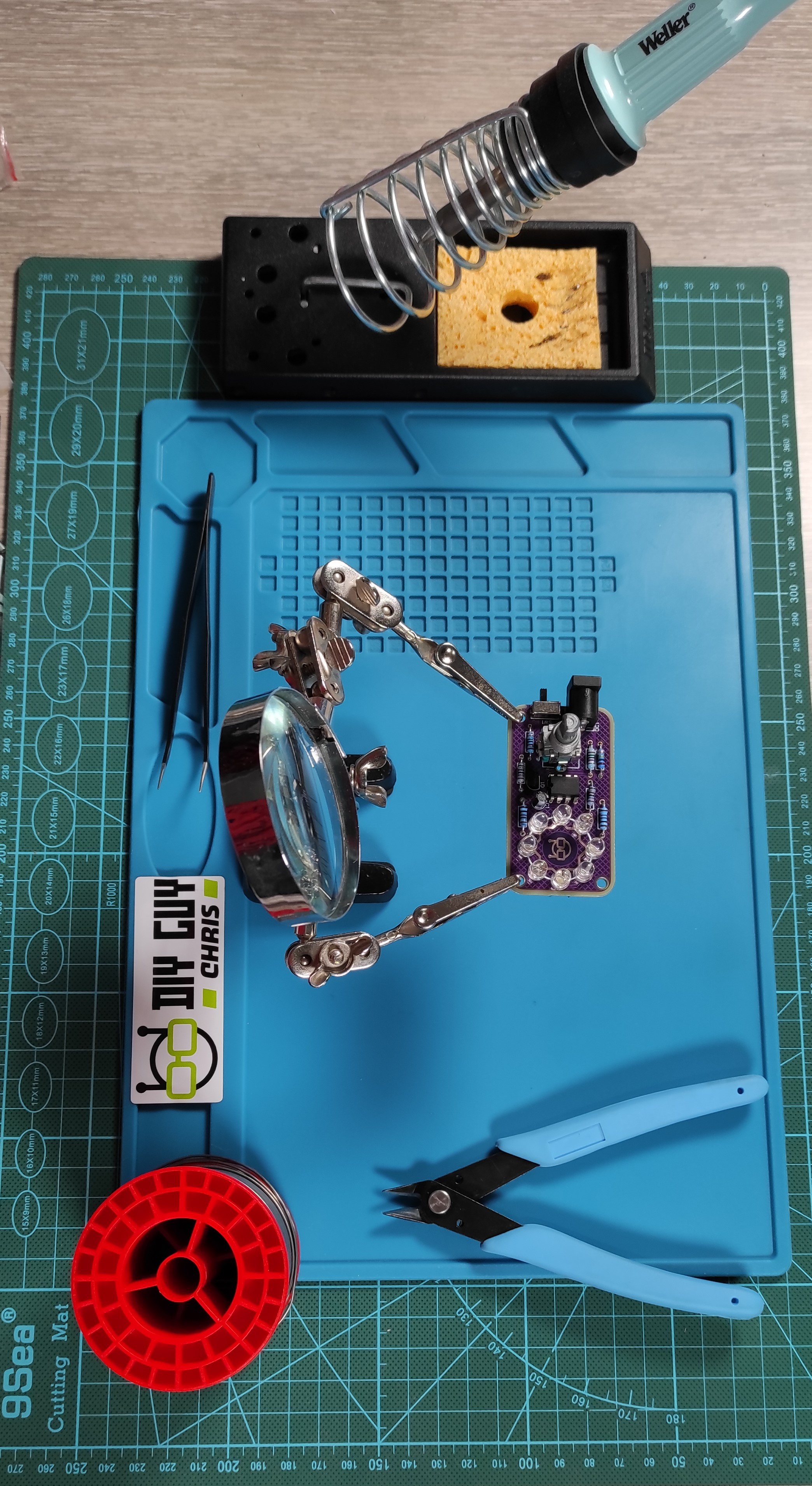
Basically the tools needed in this project are the ones related to the hardware assembly showed in the above image, otherwise you may need also a 3D printer to produce a customized housing for your device but this remains as an option.
From Breadboard to Design
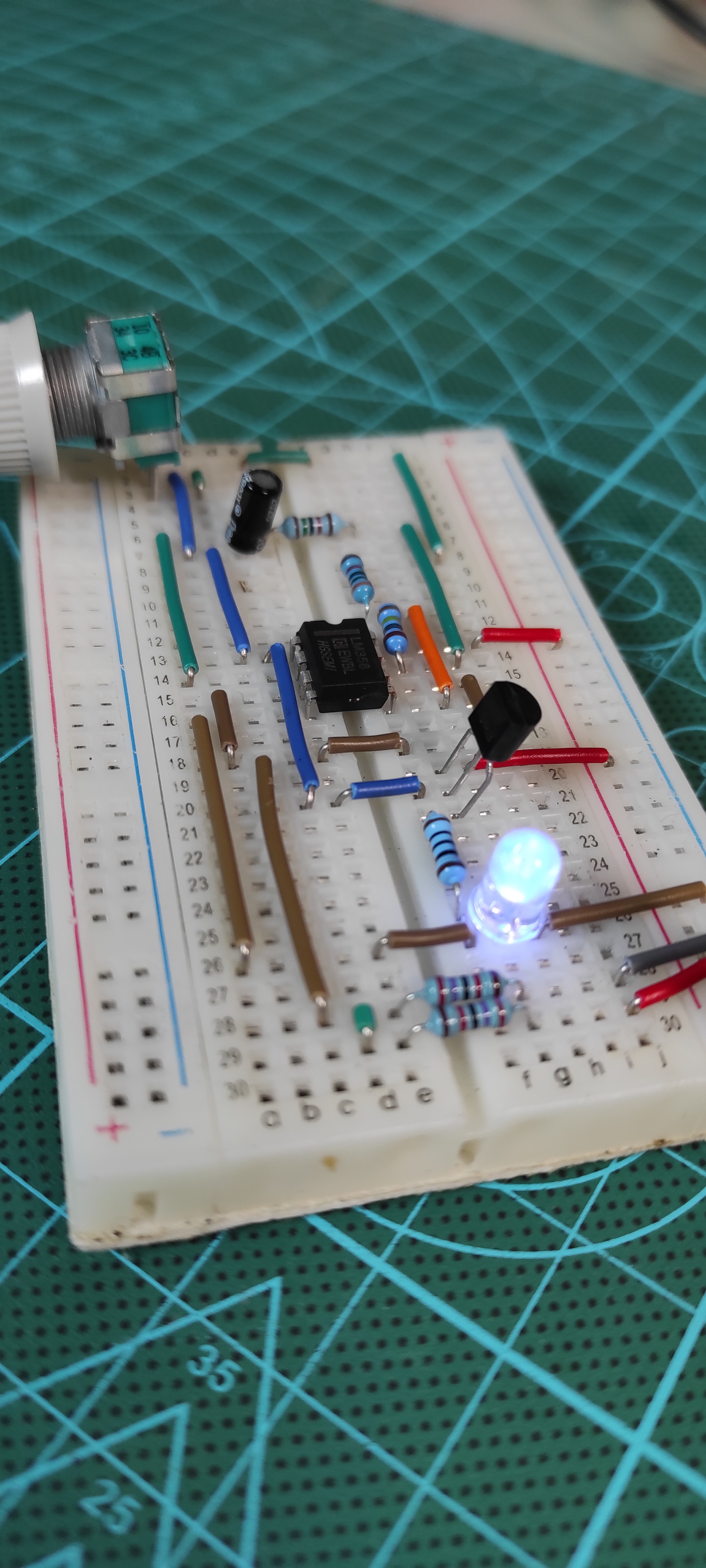
As we did in our previous projects, we always start from the breadboard by wiring the circuit parts to form the desired output function, this way we save time, debugging energy and money since we can easily modify the parts palacements and their physical values then as soon as we confirm that everything is okay to go for a printed circuit board design we can do that the easy way.

As I mentioned in the project intro, our circuit is based on the LM358 operational amplifier configured as multivibrator to produce a feed-in feed-out lighting control through its dual integrated amplifiers by producing its own input signal with the aid of an RC feedback network connected to the inverting input of the operational amplifier and a voltage divider network connected to the other non-inverting input, this setup will allow us to control the square wave frequency generated from the amplifier to control the emitter-collector junction opening of an NPN transistor where we will place our LEDs, in case you deal with a large number of LEDs then maybe you want to connect them in series to balance the current flow and ensure that they all give you the same brightness.

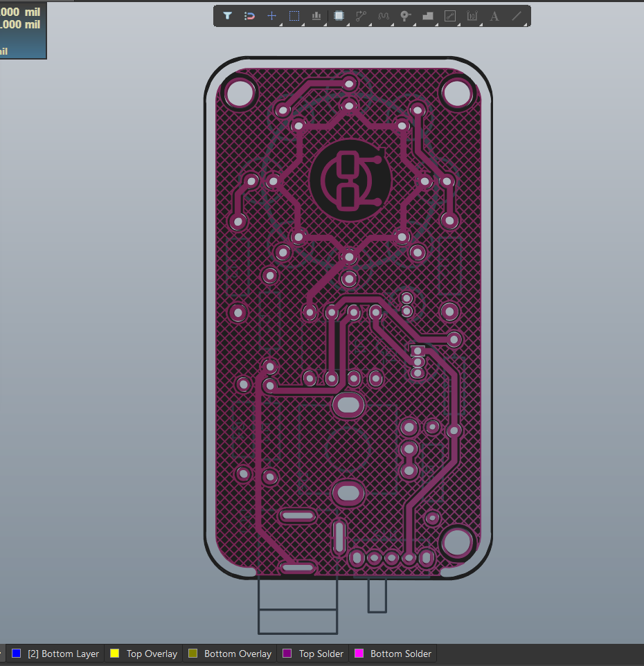
I moved to altium designer and I brought the LM358 amplifier from the online library, it comes with its inner dual amplifier blocks displayed separatly so it helps me in the schematic wiring, after establishing the parts connection I then transformed the schematic to a PCB design and I performed some PCB art drawing in there to give a cool looking to my circuit board.
Prepare for Assembly
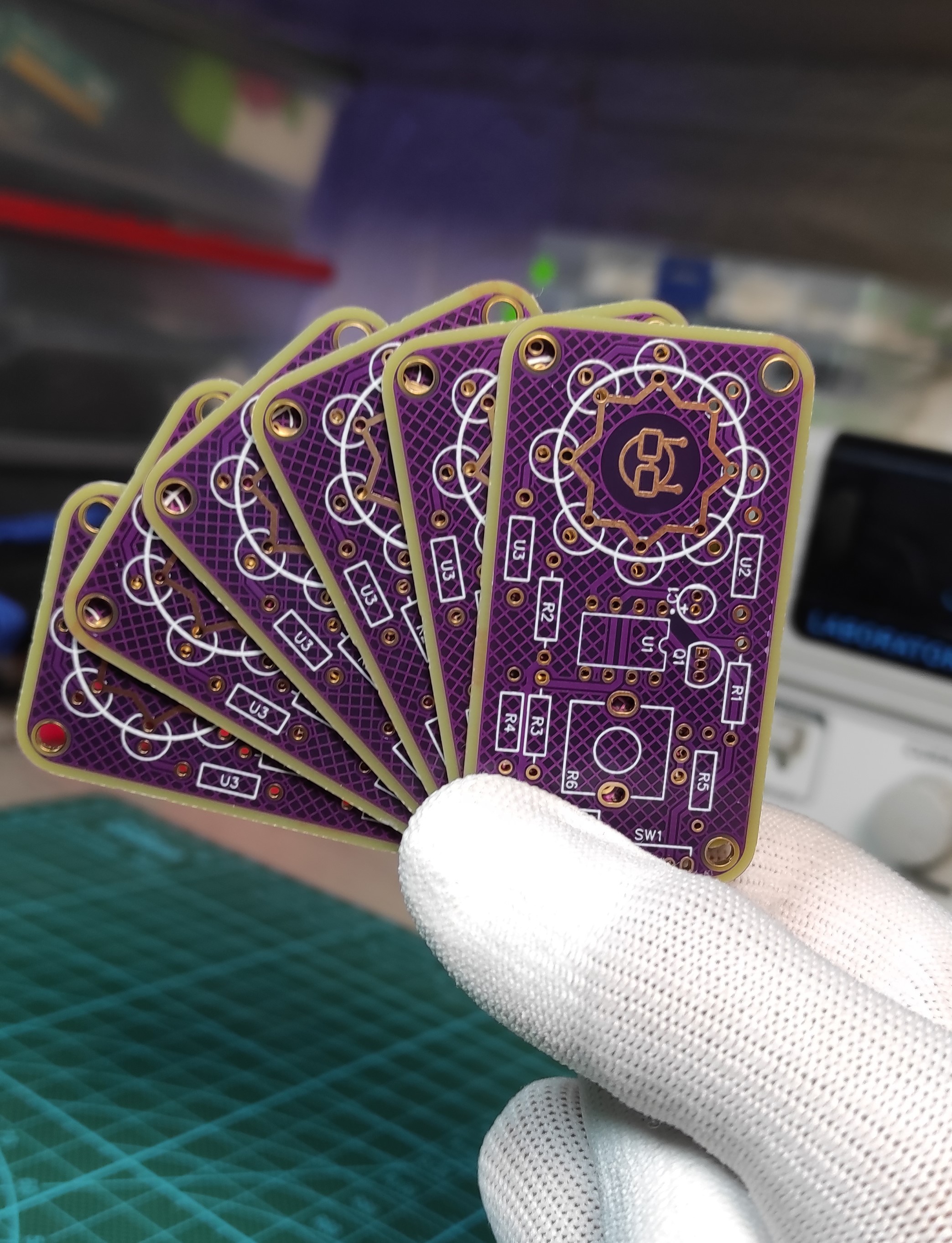
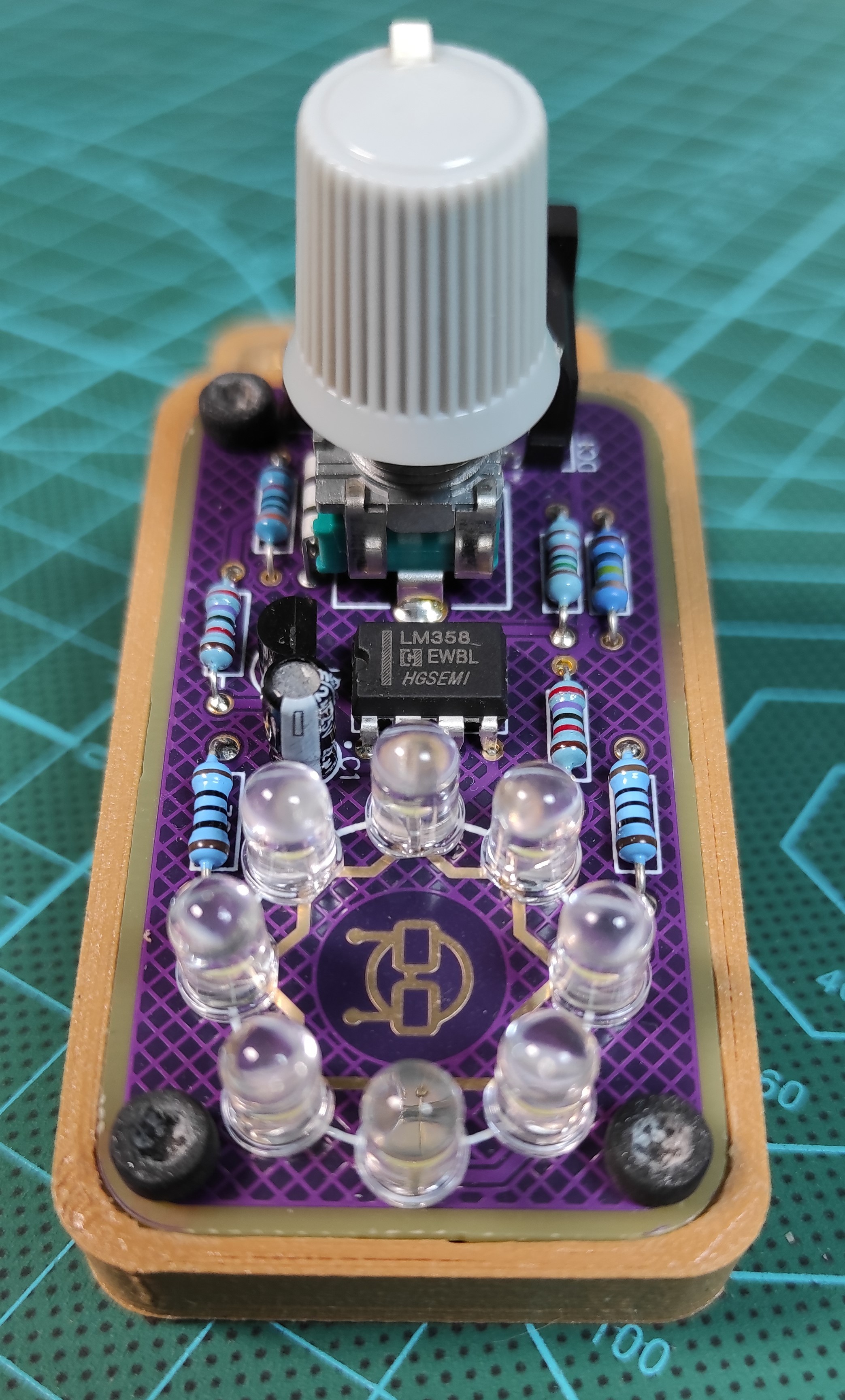
After getting the design ready, I then moved to JLCPCB where I uploaded the GERBER files of my design to get them produced, I selected the purple soldermask color for this circuit but you still can select whatever color suitable for you.
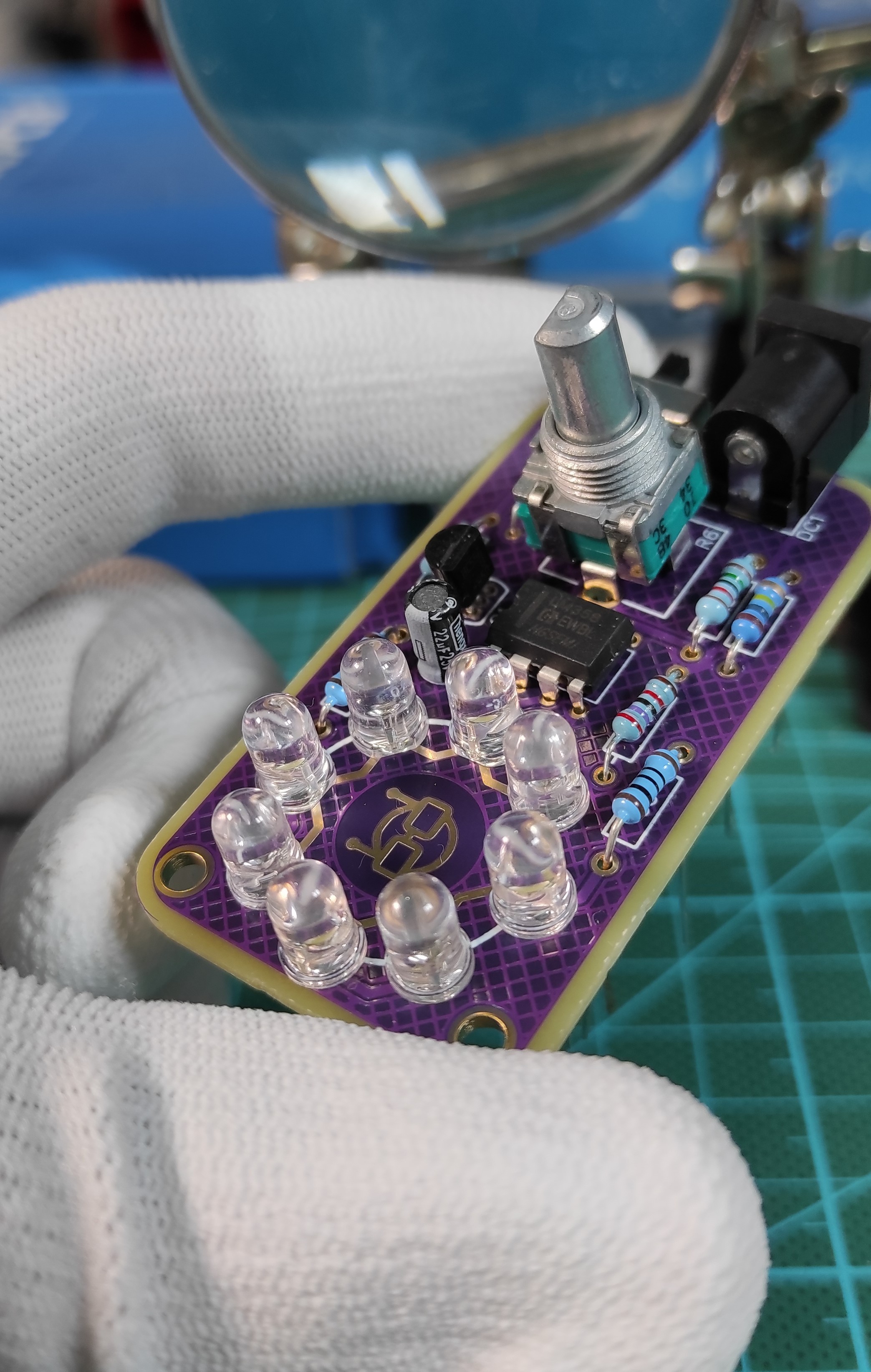
As soon as I received the PCBs I set my desktop for the assembly and I brought the tools to solder the electronics parts each to its placement on the board.
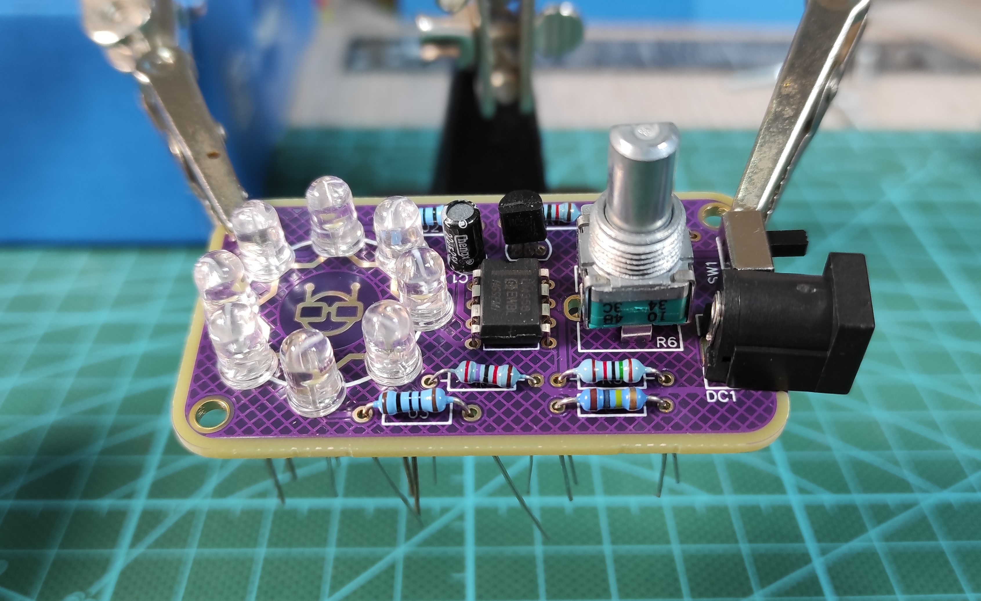
Note: You need to keep your soldering iron nice and clean. That means wiping it on the sponge every time you use it. The tip of your soldering iron should be clean and shiny. Whenever you see the tip becoming dirty with flux or oxidizing, that means losing it's shininess, you should clean it. Even if you are in the middle of soldering. Having a clean soldering tip makes it easier to transfer heat to the soldering target.
Make the Housing
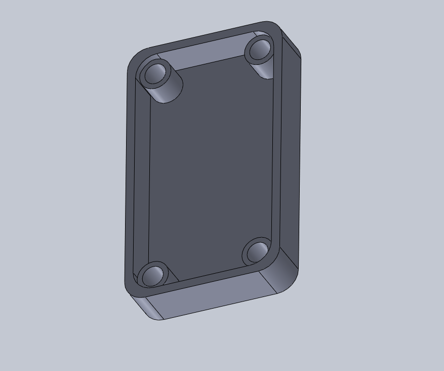
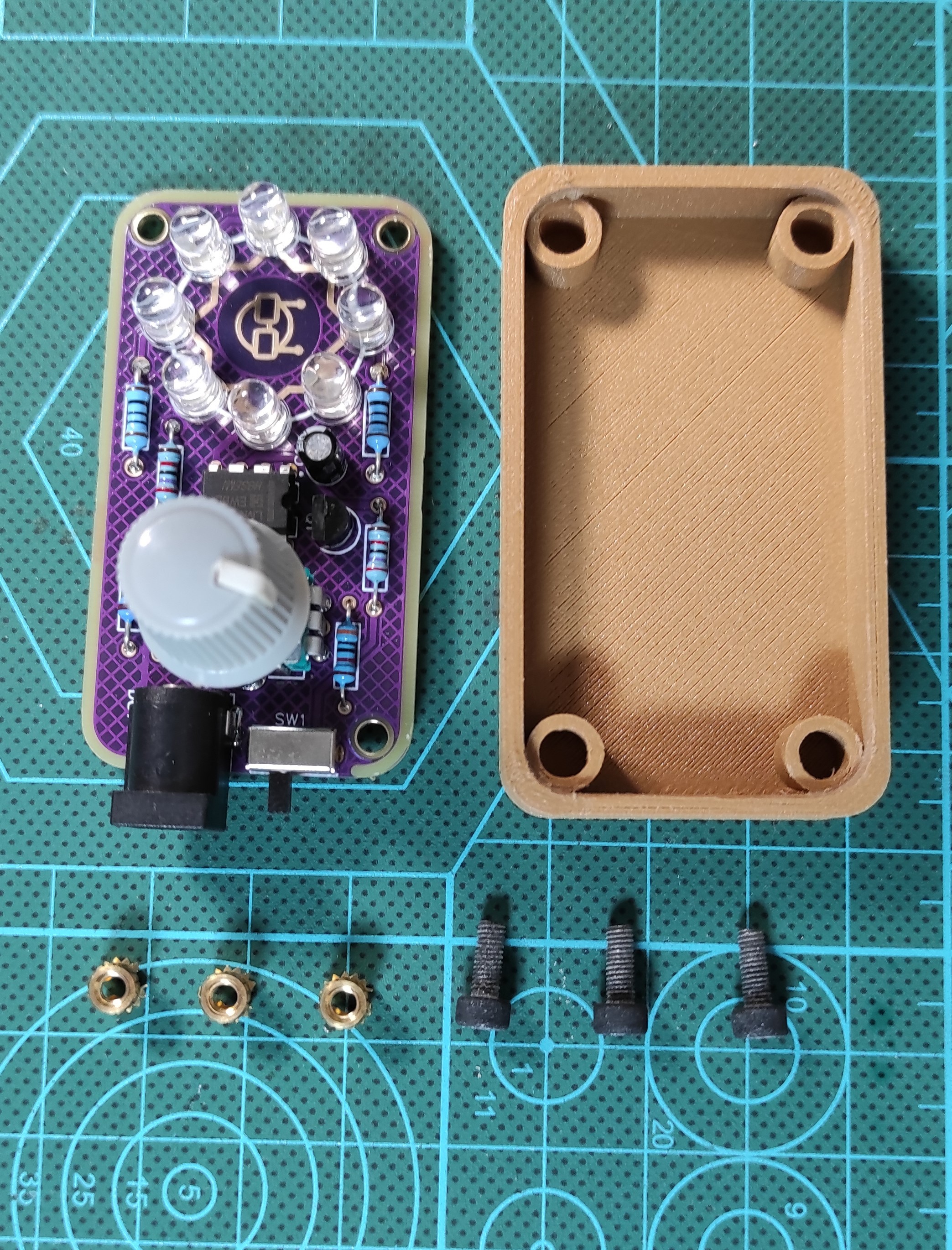
A good housing is always an advantage to your device so I advise that you design the circuit related housing and 3D print it the way I did, I used a polywood Filament to produce this housing which gives the device a better appearance then I used 3mm threaded inserts to help me screw the board to the housing and finally the device is done and ready.
Now We Test It

I added a slide switch to my device for ON/OFF control, as soon as I plug in the power jack cable of 12V DC Power supply the LEDs light up in breathing rhythm and their breathing light frequency is controlled through the rotary potentiometer then this way we successfully completed the making of this project. Any recommendations or suggestion...
Read more »

Hi!
Something wrongs: U2 and U3 is not Resistors (R)? What is the name U1 on schematics/PCB?
Nice your PCB!
Regards: DrCyberg