 Sam Ettinger
Even if you've never heard the term "TO-92," you're likely to be familiar with the shape. These friendly tripods are most often holding some type of transistor, but sometimes you see temperature probes, LDO voltage regulators, or even EEPROM in the TO-92 package. But whatever function it has, it's almost always the same boring black epoxy material. And the rare cases when it isn't boring black epoxy, it's some other color purely for utilitarian purposes. Yawn.
My original goal was to make my own TO-92 sound ICs. The quick summary is that there are some super-simple music chips with only 3 pins: power, ground, and audio output. I'm really happy with the songs I've managed to play off an ATtiny10, which critically has just 1 kB of flash and 32 bytes of RAM. There's so much I want to talk about with the ATtiny10 music chips, however, that I had to spin it off into another project writeup.
The one key detail from the sound IC project is that these sound ICs often come in TO-92 packages, which is how we got here. Originally I wanted make the most convincing production-line imitations for them, but ultimately I decided "fun colors" was way better than "authenticity". I started to want transistors that look like lee cyborg's amazing alligator clips.
What can we cram inside a TO-92?
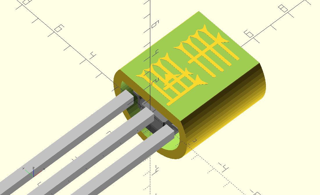
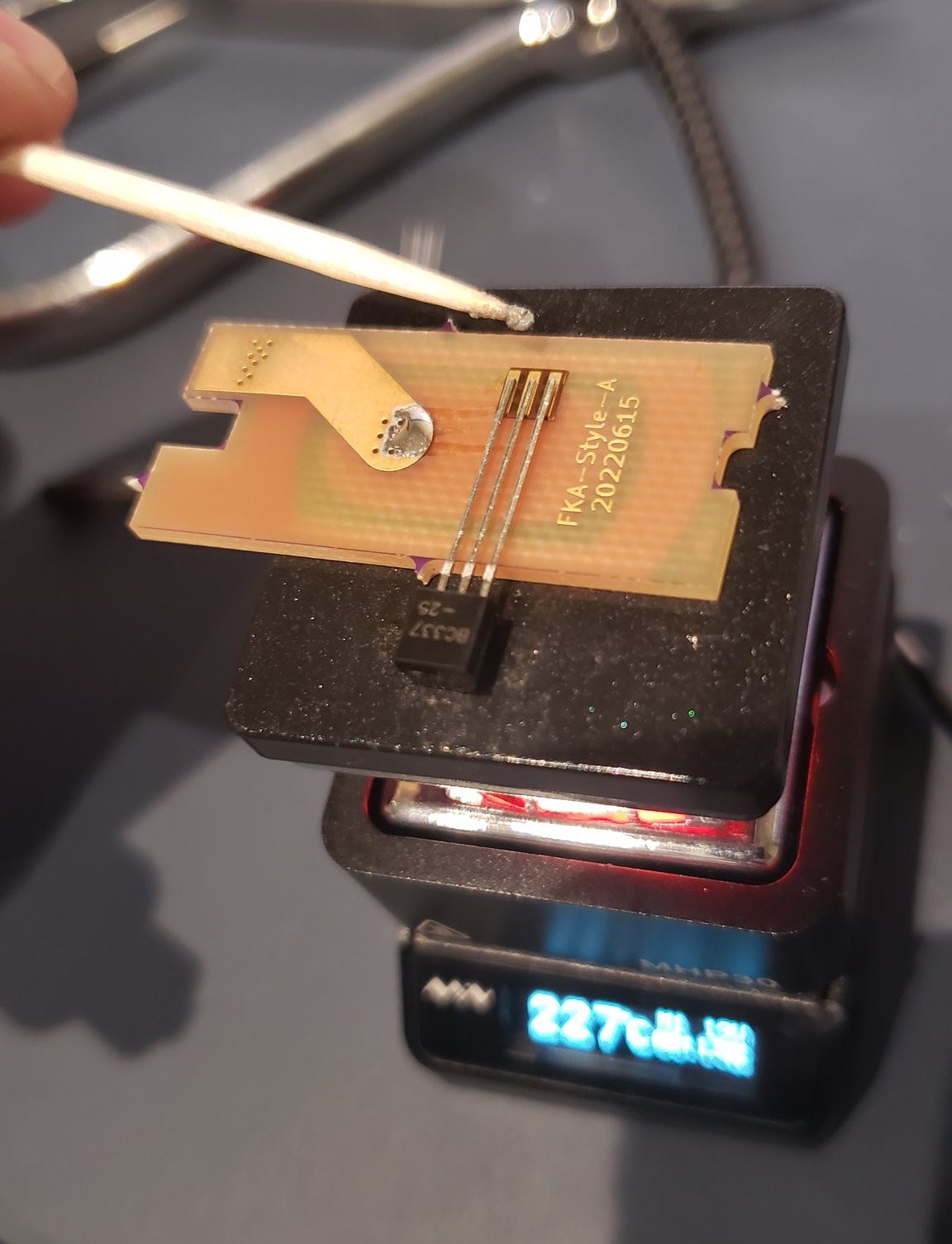
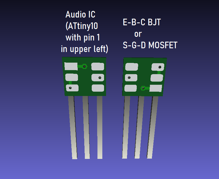
There's enough room inside a TO-92 body to house all sorts of surface-mount parts. But then there needs to be a way to connect them to the three legs that lead out of the body. My first instinct, as usual, was "make a wee PCB".


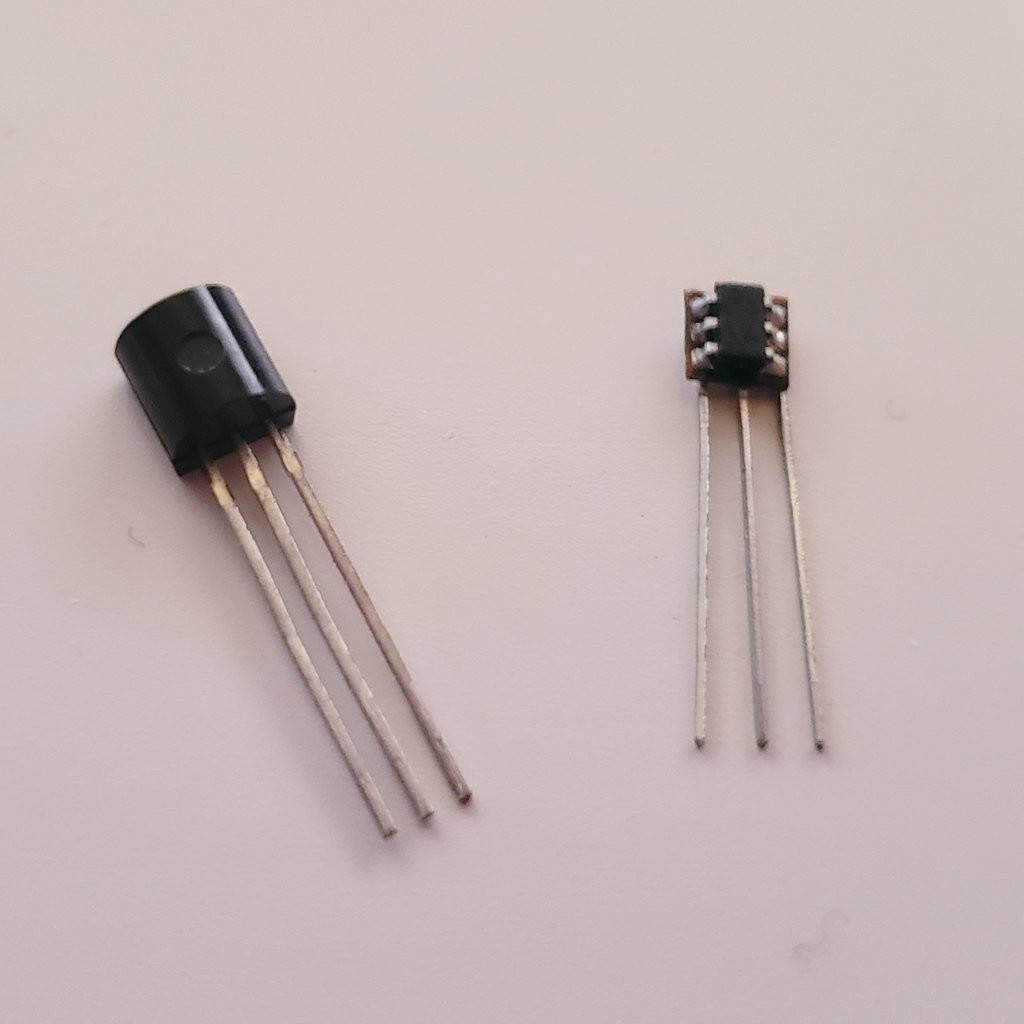
These are flex PCBs from OSH Park. I put a SOT-23-6 footprint on one side, and 3 long vertical pads on the reverse. With this, I can turn an ATtiny10 into a music chip, a B-E-C BJT into an E-B-C transistor, or a G-S-D MOSFET into an S-G-D MOSFET (two traditional pinouts for their TO-92 forms). I suppose you could also make a C-B-E BJT or a D-G-S MOSFET if you enjoy chaos. But it still doesn't look right!
Improving the TO-92ness
While visiting a good friend and Montréal maker, I did this earnest, clumsy attempt at building a mold and casting a chip in 2-part epoxy.

I think if I kept at it, I could have perfected my technique and gotten consistent good results. Maybe. But things got in the way and I lost interest in this approach. And then I got consistent access to a pretty-nice SLA 3D printer, which meant I could make detailed thin-walled prints like this:
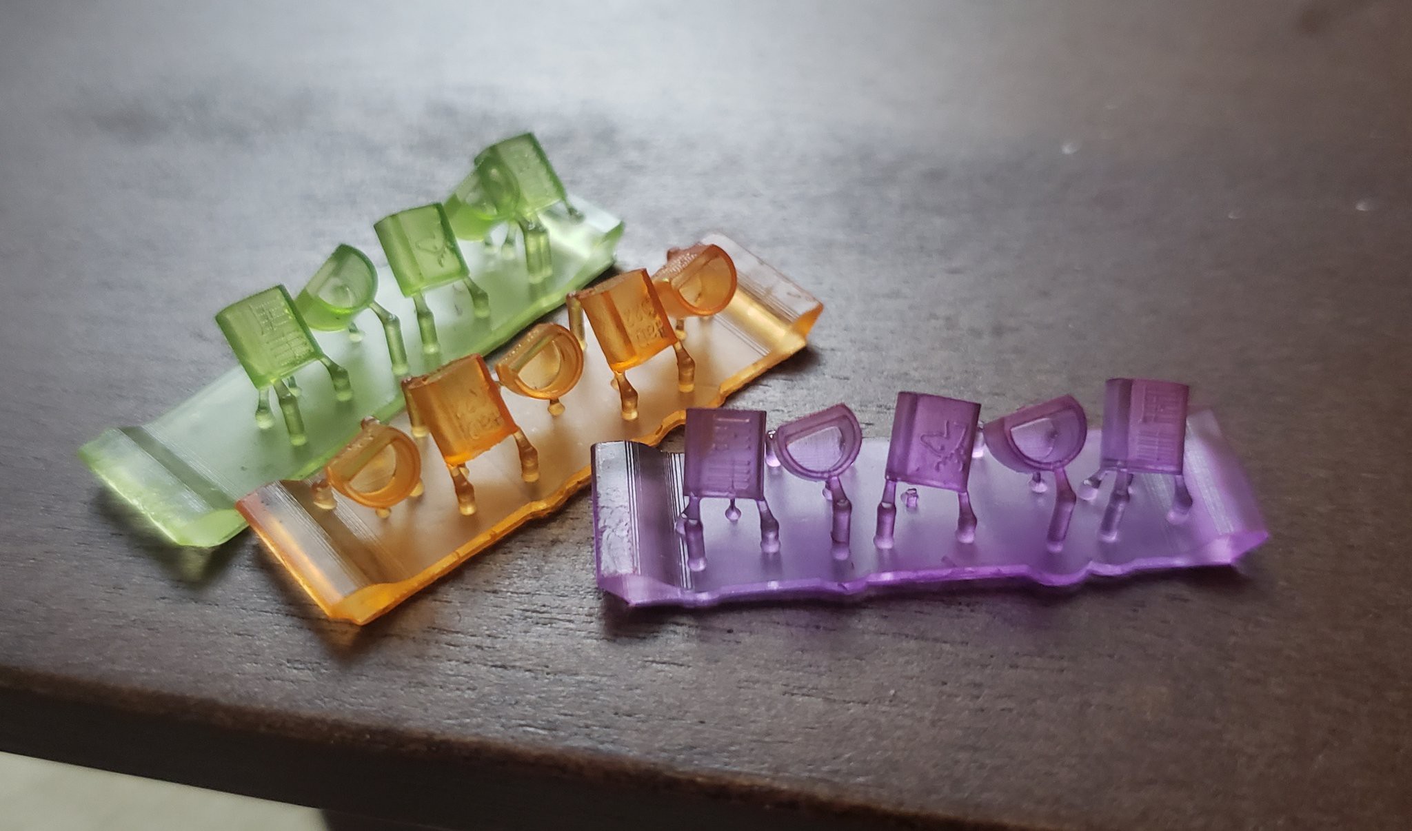
You can make them yourself, the files are on Printables. I'm so happy with these little caps, they fit so nicely over the wee PCB without any play. And printing in clear resin means I can dye each individual batch without much fuss!
Which is how we got these 🏳️⚧️transistors🏳️⚧️

And, critically, they're still functional!

Package markings
Every chip package needs some identifying marks, right? I can fit three lines of four characters on each package, more or less. Orrrr I could do something like this:
Emily Velasco found these Sumerian logograms: 𒀾 aš "curse," 𒅖 sahar "sand". Cursed sand, that's what silicon chips are, right?
Some of the other chips just say "HaD 22" because I plan to hand them out at Supercon 2022. Others have the Linear B 𐂂 deer ideogram 𐂂.
Future work: Mass production? Leadframes?
Right now, my only plan for these things is to give them away to friends. I'd LOVE to coordinate a short manufacturing run of colorful transistors and sell them as a fundraiser for some queer- and trans-focused charities I'm fond of. But I don't know how to turn this into something a factory can manufacture! Could I call up an electronics packaging factory and ask them to churn out some pink, purple, orange, etc. transistors?
For now if you really want one, your best bet will be to find me at Hackaday Supercon 2022, which is a little over a week away at time of writing.


 Elliot Williams
 Dan Maloney
 Michael R Colton
 Franklinstein
Wow, I love this! A source for the rectangular wire should be found, because, one day, there are no more of the guys to sacrifice for their own recreation! ;-)