Jithin Sanal
Circuit
Now, lets me show you the circuit first!
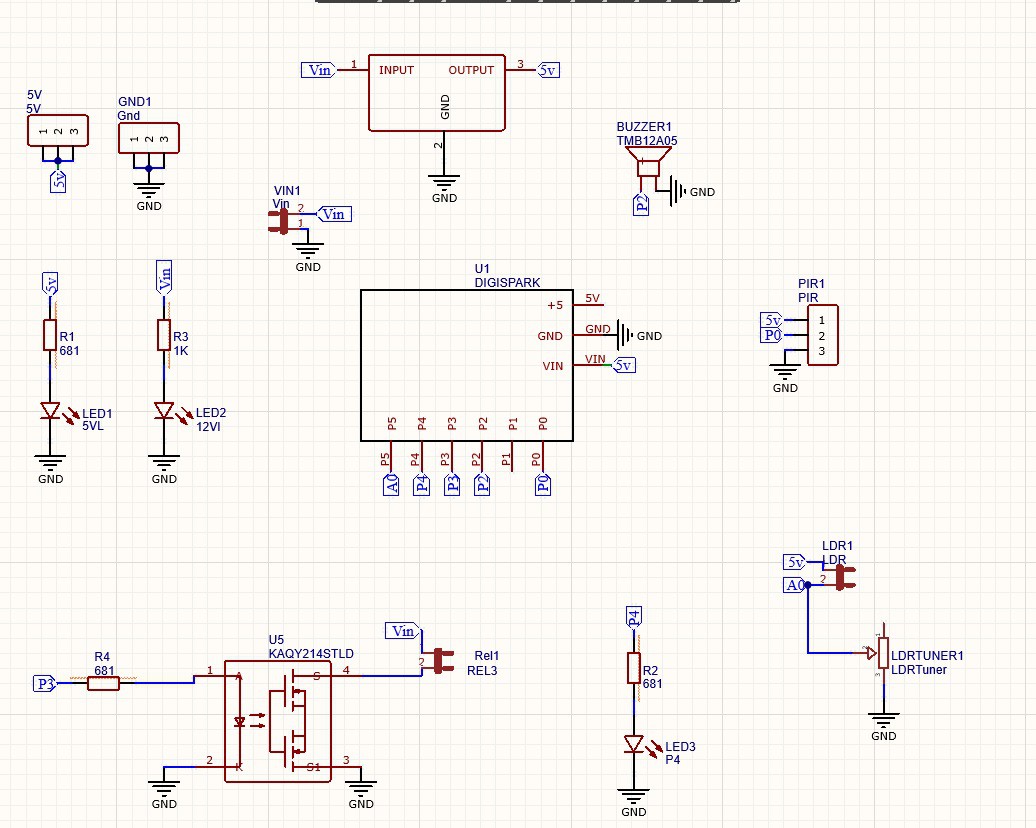
The input power is connected to a 7805 regulator. 7805 is a 5V regulator which will convert an input voltage of 7- 32V to a steady 5V DC supply. So, you can connect an input voltage of anywhere between 7V to 32 to this circuit. For this circuit, I prefer a 9V DC Adapter. There are indicator LEDs across various points for easy troubleshooting.
This is where we connect our digispark. Digispark is a new lightweight microcontroller development board. Digispark comes with 6 GPIO pins, I2C and SPI serial communication, and a USB interface.
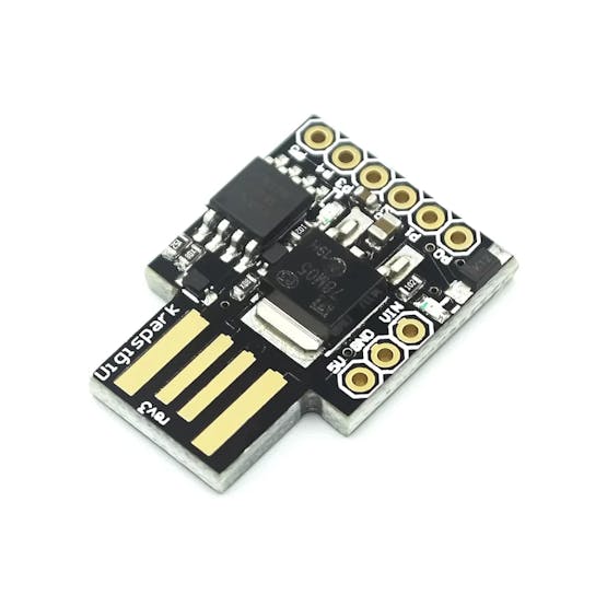
It also has 3 PWM pins, which can control l293d motor drivers or servo motors. we can use Arduino IDE to program digispark but the way we upload the program is a little bit different than usual Arduino. I have explained how it is done in one of the previous videos so you can check that out if needed.
PIR Sensor
This is the sensor that will be triggering our action.
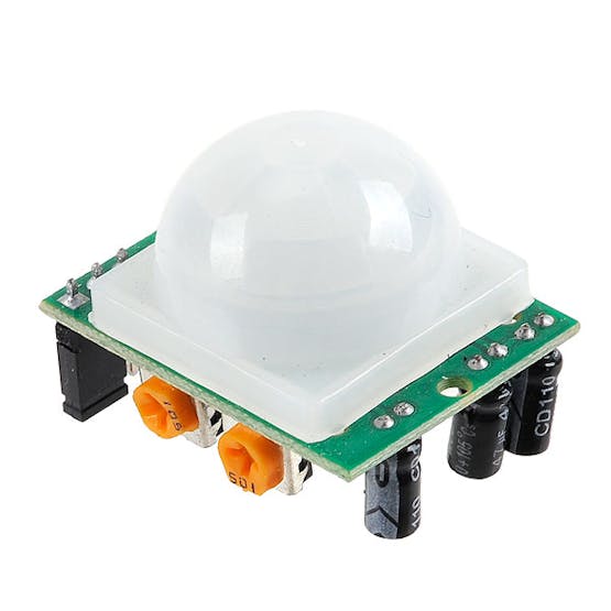
A PIR sensor is a tiny circuit that can detect human beings moving around in front of it within a range of range is between 4 Meters and 13 Meters.
There are mainly 3 pins to PIR Sensor –
- VCC – Where we connect 5 V Power Supply
- Out – Output Voltage (5V when it detects human IR Signature)
- GND – Where we connect -ve Terminal
The PIR is connected to pin P0 of Digispark, which acts as the trigger, and pin P3 is connected to the relay, which will be connected to the actuator or circuit that does the output operation. Here, you will also see a buzzer connected to Pin P2 and an LDR connected to the Analog pin of Digispark if you want to play with lights as well. Also, you will see a potentiometer with which we can adjust the sensitivity of the LDR.
Basically, that’s all I needed for this project. If you are planning on making it, make sure you try it out on a breadboard and once you get the output you can use it as such or create your own PCB.
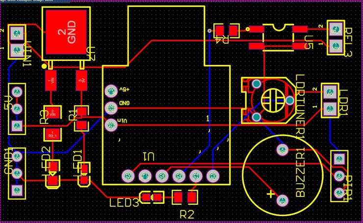
I personally like PCBs. PCBs are neat and help to get rid of all nasty wires hanging around. And it’s cool to make your own PCBs for your project right? Once the circuit was finished and tested, I designed a compact PCB using Altium, where I can fix all the components neatly. Here you can see routing is on both sides of the board which means it is a dual-layer PCB.
Getting PCB Done from PCBWay
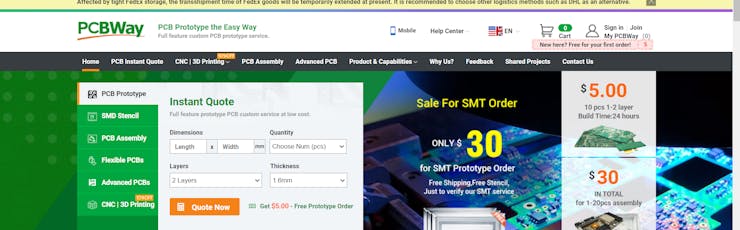
I ordered my PCB from PCBWay. PCBWay is a PCB manufacturer specializing in PCB prototyping, low-volume production, and neat and tidy PCB Assembly. To order your PCB from PCB way, Go to the PCBWay website and fill in the basic board details in the instant order form.
And in the next screen, you can completely customize your PCB. You can change the thickness, change the solder mask color as well as the silkscreen color, materials used, you can customize it in every way possible. Corresponding prices will be updated here in real-time. In PCBWay, you can even manufacture your PCBs with TG 150-160 for the same prices as that of TG 130-140 which means your PCB will be able to operate at high temperatures without any damage.
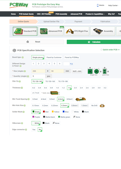
In the next screen, you should be able to upload your Gerber file and submit it for review. Once the review is completed, all that is left is to add to the cart, make the payment, and wait for your PCBs to arrive.
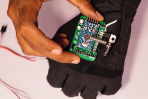
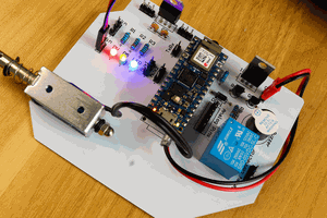
Once you get all the components and the PCB, it’s time for you to solder them together. Solder all the components onto the board and make sure to check the polarity of the components. After soldering the PCB looks like this.
Coding
We can now upload our code to Digispark. If you dont know how to set up Digispark, check out the video attached.
void setup()
{
pinMode(0, INPUT);
pinMode(4, OUTPUT);//LED
pinMode(2, OUTPUT);//buzzer
pinMode(3, OUTPUT);//relay
pinMode(1, OUTPUT);//inbuild LED
}

void loop()
{

int pir=digitalRead(0);
if(pir==1)
{
digitalWrite(4, HIGH);
//digitalWrite(2, HIGH); //Uncomment If Buzzer is Needed
digitalWrite(...
Read more »
 Sagar 001