 plugg.ee Labs
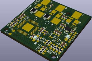
Currently I'm writing up the architecture, defining board the control system IO requirements. Here's the initial top level block diagram
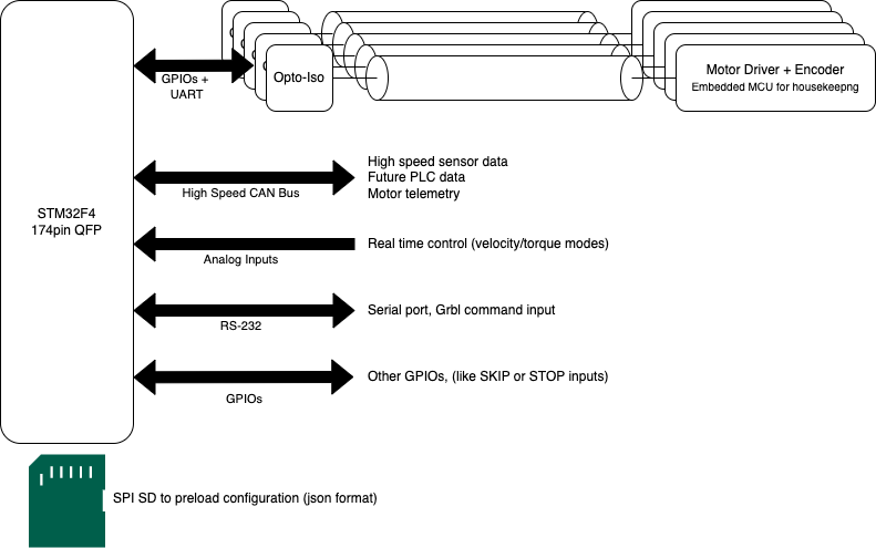
The main features of the board
1- The system will be composed of 2 fundamental components
1a- The control board: includes the same powerful STM32F4 microcontroller, all power components (motor driver, decoupling caps) will be moved to individual slave motor driver boards (1b). The board doesn't need to be powered by high voltage, although in order to power the whole system with a single supply it will most likely include an efficient buck regulator. IO's to the slave motor boards will be optically isolated to allow operation with separate power domains (immune to ground shifts), and will be shielded to reduce noise injected by motors.
1b- Slave motor driver board(s): Every motor will need it's driver board and position encoder. This gives some flexibility to the system, we can combine different motors with different requirements. The slave board will have opto-isolated IOs to the control board (DRV8301 phase control, encoder ABZ), it will also have a tiny microcontroller for housekeeping (configuring the driver, sensors and other telemetry), it will interface with the main control board through opto-isolated UART.
2- The control board will have the following interfaces
2a- High-speed CAN bus: it can connect to multiple sensors (like an IMU) for realtime feedback, can be used to feed external systems with full telemetry data. It WILL be used in the future to allow another PLC system with 24V IOs to have realtime access to all motion parameters.
2b- Analog inputs: these can be used for realtime analog driving of motors in different modes, such as position, velocity or torque. Motors can be repurposed for different applications to act like powerful servos, speed motors (like drones) or torque driven (multi-wheel vehicle with torque distribution)
2c- RS232: still under review, this allows simple gcode interpretation and driving multiple axes in a coordinated motion. Although useful, this system alone cannot be used to drive CNC applications (like 3D printer) which requires other features (like programmable IOs, MCODEs ... etc), this in turn drives the requirement for a future PLC system that sits on top.
2d- GPIOs: these are general purpose, can be use for functions like stop motion, triggers and alarms.
2e- SD card: this doesn't exist in ODrive (as it relies on storing parameters inside internal flash). We feel that this will be needed in the future, maybe it can be used for programming macro commands
Requirements are still changing, we will start component selection and design work within days. PCB design will be done using KiCAD 6, project files including firmware will be hosted on bitbucket.org
any feedback and early interaction is welcome, I may follow up with a discord server link if there's a need
 Bharbour
 Lex Kravitz
 Alberto